BACKGROUND
I chose to perform a topology optimization on a crutch design to determine the optimum material placement that minimizes volume and maximizes stiffness. It was my interest to see if the result of the topology optimization was similar to the current crutch design and in what way these designs differed. The project was performed using the software, Inspire. The crutch dimensions and loading conditions implemented into the Inspire model, mimic that of a crutch being used by a 5’ 1”, 120-pound individual. This weight was based on the fact that the crutches used for dimensions were for a 5’1” patient and that the average weight of a someone who is 5’1” is approximately 120 pounds.
Measurement Procedure
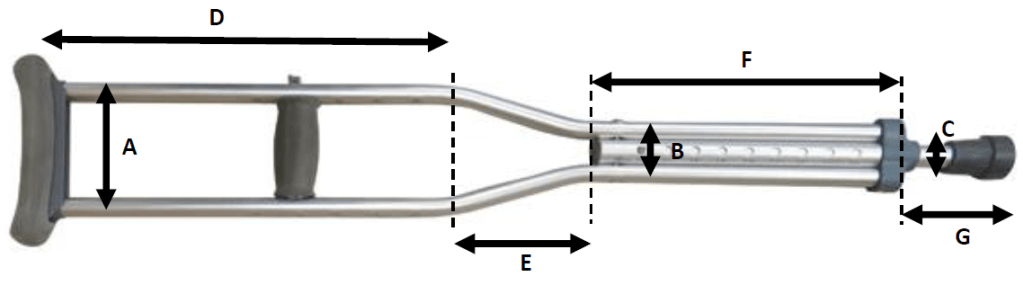
Dimensions were obtained from a pair of crutches used by my brother. A visual representation of these dimensions can be seen in Figure 1. The corresponding value to the lengths depicted in Figure 2 are displayed in Table 1. The overall thickness of the crutch was 0.75 inches.
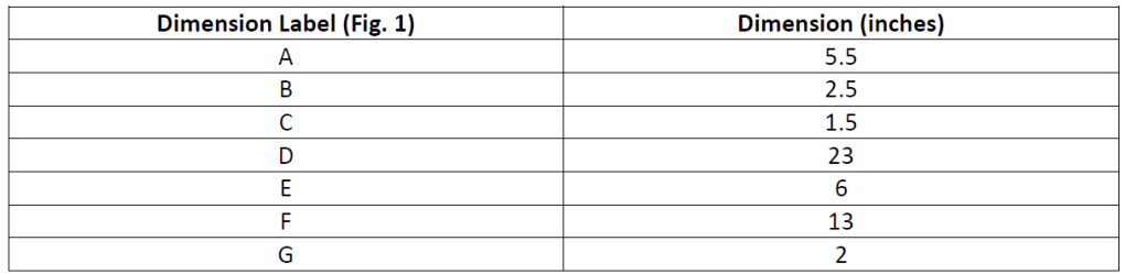
An appropriate moment arm needed to be measured and defined. Every time the crutch is used it has a pressure acting on the end that sits under the arm of the user. This pressure causes a moment. The moment arm is depicted in Figure 2. Being 5’1” myself, I measured the moment arm I created while using the crutches. Varying results were found, with the moment arm being in a range of 8 to 14 inches, with 14 inches essentially being the maximum moment arm a 5’1” individual can comfortable make and still operate the crutches in the appropriate manner. 14 inches was chosen to be the moment arm for the Inspire model since it represented the maximum value and therefore the worst-case scenario with regards to the magnitude of the applied moment.
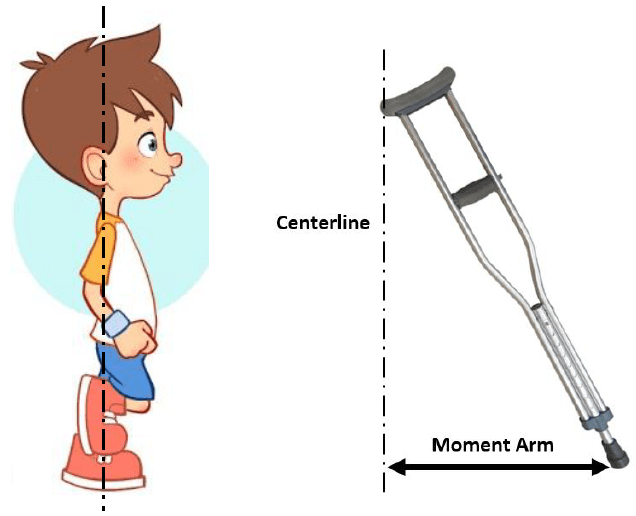
Figure 2 displays how the moment arm was measured. It was measured from the centerline of the user to the tip of the extended crutch. The weight of one crutch was measured to be 2.1 lbs.
Procedure of First Attempt
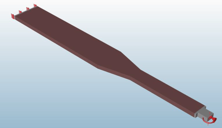
The first Inspire model (Fig. 3) was created to be bulky, in the hopes of seeing whether the software could create a design with the features seen in a crutch.
The design space in Figure 3 measures 42 inches long, 5.5 inches wide, and 1.5 inches thick. The end of the design that represents the tip of the crutch, measures 2 inches long and 1.5 inches thick. Flanges were added to the tip for support and are 0.5 inches thick and extend 2 inches out on either side. The magnitude of the moment was calculated by multiplying the weight of the user acting on the crutch, 60 lbs, by the moment arm, 14 inches. This calculation yielded a moment with a magnitude of 840 lbf-in. The moment was applied in the middle of the tip of the crutch. The tip was also fully constrained at the tip face.
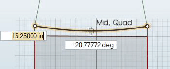
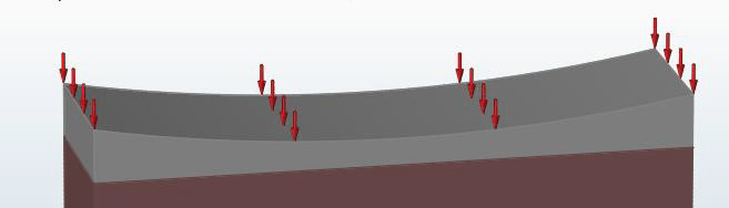
The end of the design that represents the part of the crutch that sits under the user’s arm had a pressure applied to it of 7.2 psi. This was calculated by first determining the area of the end by determining the arc length (Fig. 4), 5.53 inches, and multiplying it by the thickness of 1.5 inches. Since pressure is force over area, the 60 pounds of force was divided by the area which results in a pressure of 7.2 psi. Figure 5 is a close up image of the applied pressure to the crutch.
The model material was assigned as Aluminum 7075. The mechanical properties of Aluminum 7075 are seen below in Table 2.

The model was analyzed and the max Von Mises stress, mass, and minimum factor of safety values were recorded. Optimization was subsequently performed on the design space with a single draw manufacturing constraint. Holes were allowed since the goal was to minimize mass and the design that was being attempted to replicate had holes. Three separate optimizations were run, each with a different single draw direction. The results for each were also analyzed and the max Von Mises stress, mass, and minimum factor of safety values were recorded.
Results of First Attempt
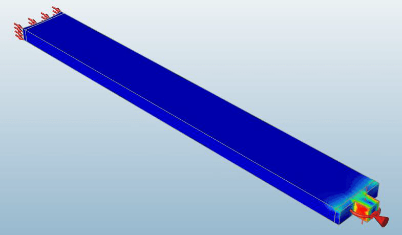
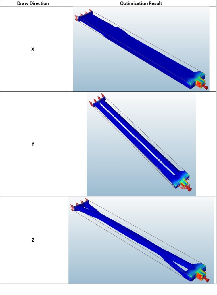
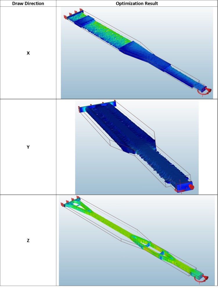
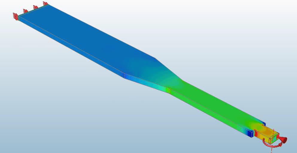
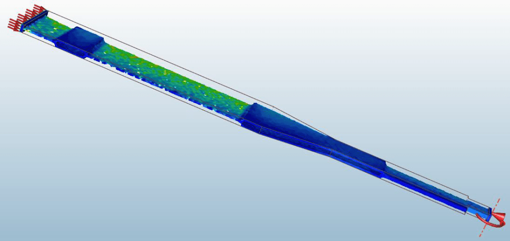
The geometric results of each optimization with their stress contour plots can be viewed in the following table (Table 3). The stress contour plot of the original design can be seen in Figure 6.
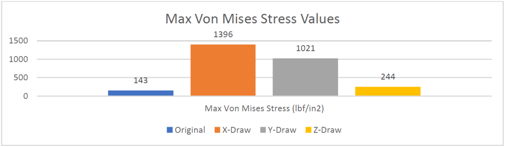
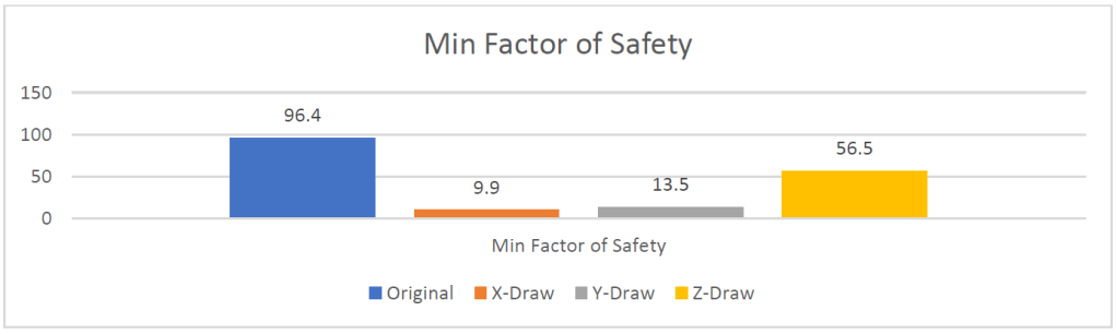
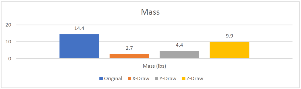
The analysis results for each optimized design include the max Von Mises stress, mass, and minimum factor of safety values. These results are depicted in the following figures (Figs. 7-9).
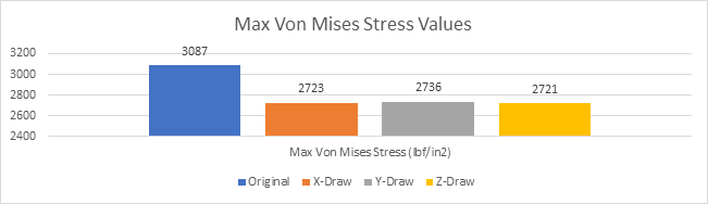
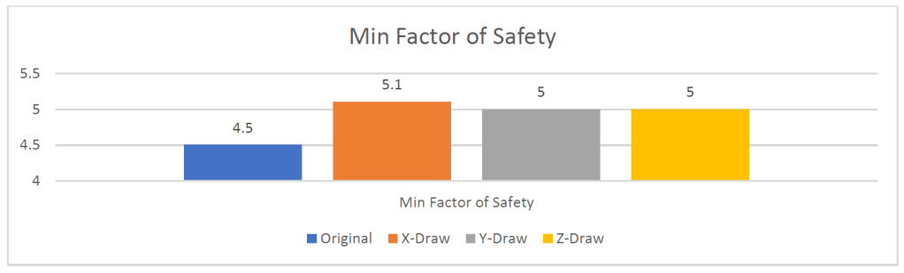
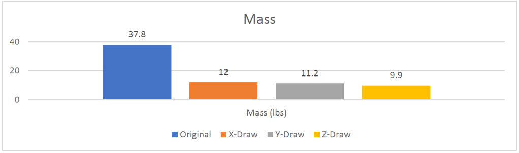
All the optimized designs were structurally sound due to the factor of safety being greater than 1. The mass of the design was decreased in all the optimized designs but the lightest design, Z-draw, still weighed a hefty 9.9 lbs. This weight is not similar to the crutch design that is being attempted to replicate. In addition, the shape of the optimized designs (Table 3) don’t bear any resemblance to the crutch pictured in Figure 1.
Procedure of Second Attempt
Due to the optimization results of my first attempt failing to resemble the crutch design seen in Figure 1, a different approach was used. A less bulky and defeatured design would be used in this attempt (Fig. 10), with the hopes of the optimization result resembling the standard crutch design. The thickness of the design was decreased to 0.75 inches, which is the same thickness as the crutch pictured in Figure 1. Since the thickness decreased by half, the applied pressure doubled. The moment and applied constraints did not change.
Results of Second Attempt
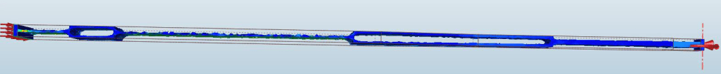
The geometric results of each optimization with their stress contour plots can be viewed in the following table (Table 4). The stress contour plot of the original design can be seen in Figure 11.
The analysis results for each optimized design include the max Von Mises stress, mass, and minimum factor of safety values. These results are depicted in the following figures (Figs. 12-14).
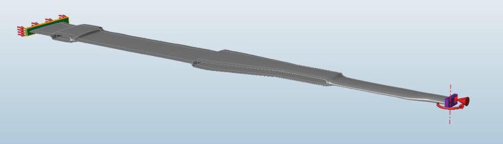
All the designs were structurally sound given that the minimum factor of safety was greater than 1 for every design. No optimization, though, resulted in a design similar to that of Figure 1. The design that performed the best was the optimized design manufactured by a x-direction single draw. This design only weighed 2.7lbs. This design can be viewed in the following figures (Fig. 15 & 16).
PolyNURBS was then used on the optimized design to create a smooth geometry. The result of this process is shown in Figure 17.
An analysis was performed on the PolyNURBS design. Mass, max Von Mises stress, and min factor of safety were recorded with this analysis. These results are reported in the following table (Table 5).

Conclusion
Two attempts were made with the hopes of directing Inspire to create a similar design to the standard crutch design (Fig. 1). Inspire was not able to replicate the standard crutch design. However, one of the designs Inspire did formulate was similar in mass to the standard crutch design. The formulated design had a mass of 2.9lbs while the standard crutch design weighed 2.1lbs. There are a few possible reasons why Inspire failed to produce a similar design. It could be due to the minimum member size, valuing maximizing stiffness over minimizing mass, or perhaps there was an error with the loading conditions and constraints.
There are two points that can be learned from this study. The first is that there are many designs that accomplish the same goal. The PolyNURBS design and the standard crutch design both can withstand the loading conditions. Another point that is demonstrated by this study is that design software is not perfect. The standard crutch design is lighter than the PolyNURBS design and has been used since the 1920s.
It is important to realize that design software, though incredibly helpful, is limited and does not always produce the optimum results. Design software should be utilized as a tool and not as an authority on design.
