Design Proposal
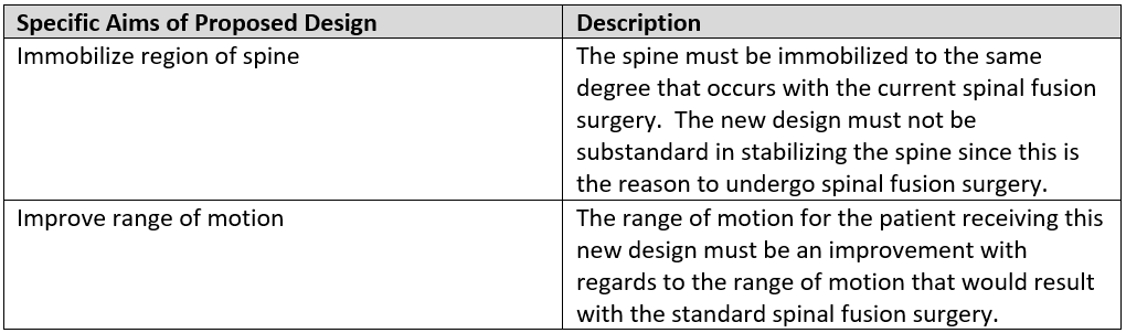
The loss of mobility resulting from spinal fusion is a cause for concern given that it has the potential to impact the quality of life a patient can lead. This concern is even more evident in the case of spinal fusion surgery done to correct scoliosis. A design for fusing vertebrae is needed that is able to immobilize a specific region of the spine without adversely affecting the patient’s range of motion beyond what is necessary. This design sets out to accomplish both of these aims, which are listed in the following table (Table 1).
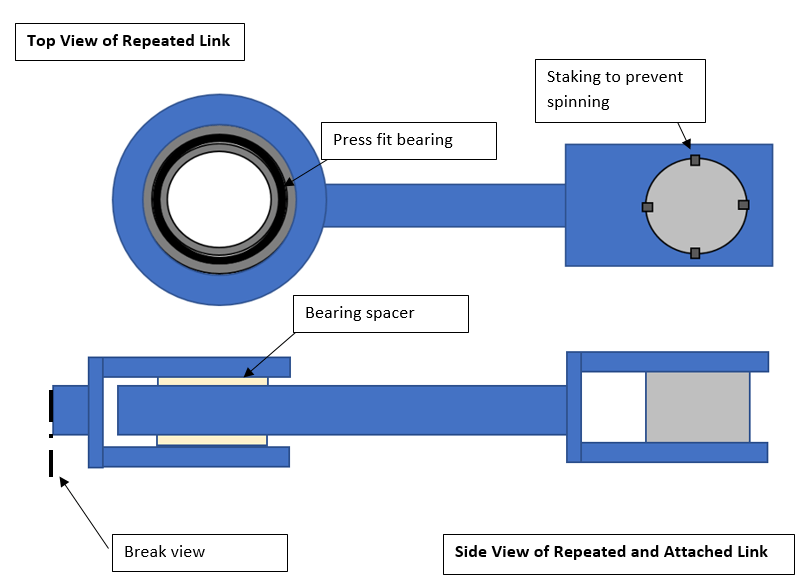
The design concept being proposed is shown below in Figures 1 and 2. The design consists of titanium links that are connected through the use of staked axles. The links pivot about the axle of the previous link through the use of press fit bearings.
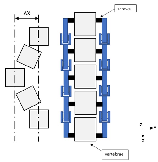
This design would be able to correctly align and stabilize a spine along with providing the patient with an improved range of motion when compared to a standard fusion. The pivot points in the design would allow for the vertebrae to move in one plane of motion instead of being constrained in all three axes, which is what occurs with fused vertebrae with a standard spinal fusion procedure. The plane of motion for the implant pictured in Figure 2 would be along the xz-plane.
The pivot locations between repeated links are locations with the highest susceptibility for failure. The reason for this is that at these locations only the bearing and the staked axle resist the force exerted by the spine as it attempts to resume its initial twisted shape. Figure 3 provides a visual representation of the forces exerted by the spine on the pivot points between links.
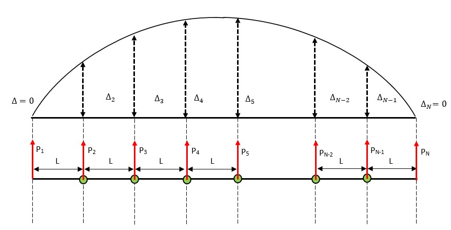
Figure 3 shows the deformed spine and its displacement from a straight spine, as well as the resultant forces on the pivot locations due to straightening the spine. The displacement values for the first and last vertebrae are set equal to zero since surgeons usually fuse the next vertebrae after the deformed portion of the spine. These forces can be solved for with Equation 1. Equation 1 is a variation of the Euler-Bernouli Beam Equation [1] with torsional rotation being assumed to be negligible.
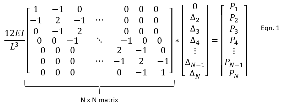
With Equation 1, the forces acting upon the pivot locations can be calculated. The variable ‘N’ stands for the number of vertebrae being fused, while ‘E’ and ‘I’ stand for the elastic modulus and moment of inertia, respectively, of the spinal column. The displacement values are indicated in Equation 1 with the delta symbol.
After the forces on the bearings have been calculated, a bearing able to withstand this magnitude of thrust force would be selected. This bearing would need to be either a four-point contact, angular, or tapered roller bearing since these bearings are the most adept at handling thrust. The bearing must be sealed to prevent grease from the bearing contaminating nearby tissue and to prevent contaminates from entering the bearing race and causing bearing failure.
To evaluate the legitimacy of this proposed design, a series of tests must be completed. The first test that must be done is a fatigue test. This test would be done by mechanically loading the linked design at the links and proceeding to cyclically bend the links for an extended period of time. After this period of time, assuming the device didn’t fail before, the device would be deconstructed and examined for signs of fatigue. The bearings would be disassembled with the inner race, the outer race, and the balls all examined for signs of fatigue failure. The goal of this test would be to find no signs of fatigue failure in any of the device’s elements.
The materials used in the proposed design would be tested for biocompatibility with a direct contact assay [2]. This test should yield no unfavorable result since spinal fusions are constantly done with the material titanium but this test should still be done to guarantee that the titanium used in this device is also non-toxic.
The device, only after passing the fatigue and biocompatibility tests, could proceed to be tested in vivo. This test would consist of the device being implanted in an animal which possesses a spine of similar size to a human. The animal would need to be monitored for pain, range of motion, and toxicity. Upon removal from the animal after testing, the device would need to be once again examined for signs of fatigue. The bearing grease would require inspection for contaminants present. Protein absorption and bone formation would need to be absent from the titanium links. If present, it may be prudent to consider coating the links with self-assembled monolayers with a D-Phenylalanine-Proline-Arginine-Proline-Glycine (fPRPG) end group [3], which is a thrombin inhibitor that could prevent protein absorption.
Spinal fusion surgery is commonly performed to improve the lives of patients. It’s possible that this proposed design would further advance the lives of these individuals and allow them to lead a life more closely resembling those who never need spinal fusion surgery.
References
[1] McGuire, William; Gallagher, Richard H.; and Ziemian, Ronald D., “Matrix Structural Analysis, 2nd Edition” (2000). Faculty Books.
[2] Temenoff, J. S., & Mikos, A. G. (2008). Biomaterials the intersection of biology and materials science. Upper Saddle River: Pearson Prentice Hall.
[3] Sidónio C. Freitas, Mário A. Barbosa, M. Cristina L. Martins, The effect of immobilization of thrombin inhibitors onto self-assembled monolayers on the adsorption and activity of thrombin, Biomaterials, Volume 31, Issue 14, May 2010, Pages 3772-3780, ISSN 0142-9612,
