Summary of Design Need
The nuisance of mosquitoes is something known across the world. In addition to being an itchy reminder of time spend outdoors, mosquitoes are vectors for a plethora of pathogens including West Nile virus, Zika virus, malaria, dengue, etc. and therefore the incidence of mosquito bites needs to be minimized. This can be achieved via three means; repellants, insecticide, and bug zappers. Bug zappers, devices that utilize light and electricity to attract and subsequently fry bugs, are commonly employed to reduce the nearby mosquito population. Users of such devices see the remains of insects stuck to the electrical wire on their bug zapper and interpret this as proof that mosquitos were killed. However, according to a study done by the University of Delaware [1], bug zappers are inefficient at attracting and eliminating mosquitoes. The study analyzed the outcome of six bug zappers during the course of 10 weeks in the respect of the number and kind of insects killed. The results were that only 31 of the 13,789 insects eliminated by the bug zappers were insects that bite humans for blood (including flies and mosquitoes). In other words, only 0.225 percent of the insects killed by the bug zappers are of the target insect population. The New York Times [2] mentions in an article about the efficacy of bug zappers that other studies done by Notre Dame and Colorado State University are corroborating in documenting the failure of bug zappers to effectively eliminate mosquitoes. Part of the reason that bug zappers have a negligible impact on the mosquito population is because mosquitoes’ attraction to UV light is one of nuance. According to a study recently completed at the University of California, Irvine School of Medicine, the spectrum of UV light that is attractive to mosquitoes depends on the mosquito sex, species, and time of day [3]. In addition, the study also shows that certain light spectra can act as a deterrent depending on the same set of variables used for light attraction.
Indiscriminate killing of insects by bug zappers can be detrimental to local ecological food chains. The University of Delaware study found that pollinators, such as moths, and insects that are a main source of food for species of frogs, bats, birds, etc. are killed by bug zappers in higher numbers than mosquitos.
There exists a need for a bug zapping device which would be able to target mosquitos without causing harm to other insect species.
Design Aspects
For a device to have the ability to predominantly target mosquitoes with little collateral insect damage, characteristics unique to mosquitoes would need to be utilized. Focusing on how mosquitoes locate humans appeared to be an ideal place to start. Mosquitoes detect humans using a combination of factors including exhaled C02, heat, human sweat, and lactic acid concentration in sweat [4, 5, & 6]. Therefore, C02, heat, and a lactic acid/human sweat analog were the design aspects that were needed to be incorporated into a new more discriminate mosquito zapper. UV light was not considered as an element for mosquito attraction in the design given its nuanced impact as an attractant for mosquitos.
User Requirements
The following user requirements (Table 1). were created to home in on the specific needs that need to be addressed with a new bug zapper for use against the mosquito population.
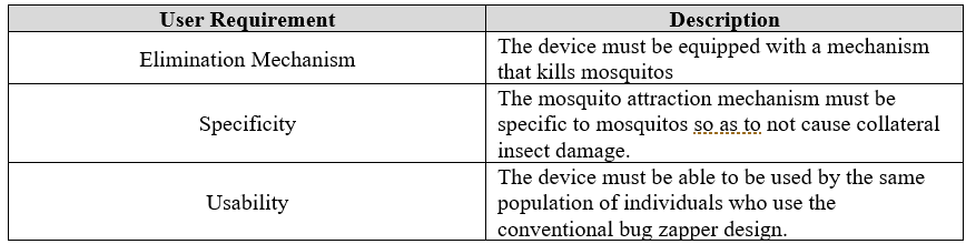
The user requirement of elimination of mosquitoes would be satisfied by the incorporation of the already existing electrical mesh wire device found in bug zapping designs given its proven efficacy at killing insects. There was no need to redesign this mechanism as the goal of this new device wasn’t so much to create a new killing method as it was to employ a novel way of specifically attracting mosquitoes and limiting the number of unnecessary insect deaths. The requirement of specifically attracting mosquitoes and only mosquitoes was to be accomplished by using a lactic acid/human sweat analog, CO2, and heat. The usability requirement would be satisfied by not having a device that mandated specific knowledge or skill beyond that of the population of individuals who currently use bug zapping devices.
CO2 Dispersal Device Design
Cartridge Holder Assembly
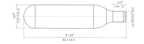
The first challenge for the design process was to create a way to store and release CO2 as an attractant mimicking the exhalation of CO2 in human breath. A C02 cartridge commonly used for air powered rifles was selected given its established availability. Specifically, the Crosman 12g CO2 cartridge [7], with its dimensions shown below in Figure 1, was to be used as the gas storage device.
Using the dimensions of the CO2 cartridge shown above a cartridge holder assembly was designed to secure the cannister for controlled release of gas. The cartridge holder design, along with the CO2 cartridge, can be seen in the figure (Fig. 2) below.
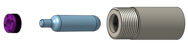
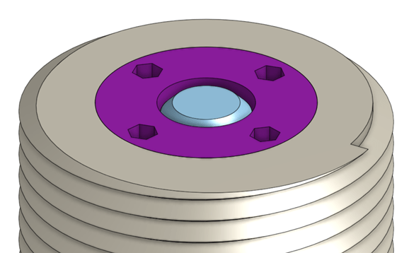
The design to secure the CO2 cartridge consists of a threaded cartridge pipe in which the cartridge fits and a threaded cap to lock the cannister in place while leaving the top open. Four 7/64 allen wrench holes for screwing in the threaded cap exist as well as a centered 7/64 allen wrench hole in the bottom of the threaded cartridge pipe to ensure a tight fit between the assembly within the dispersal device. A close-up view of the cap fitting into the cartridge pipe is seen below (Fig. 3).
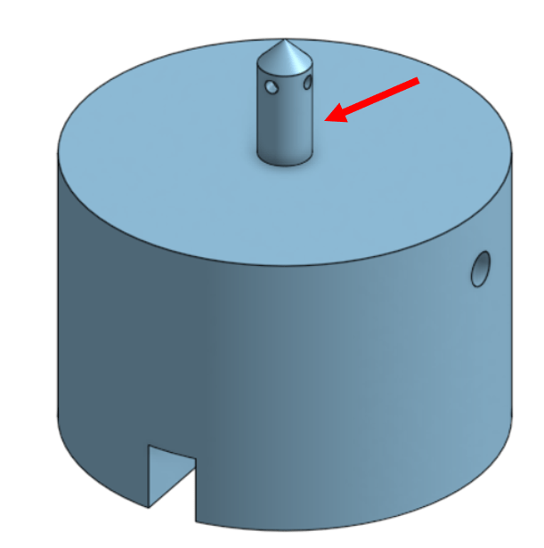
CO2 Cartridge Puncture Component
An important element of the CO2 dispersal design was to conceptualize a method to puncture the CO2 cartridge while also allowing for controlled release of the pressurized gas. The idea was to use a non-moving part that the cartridge was forced into, thus piercing it, when the C02 cartridge holder assembly was screwed into the bug zapper device. This part can be seen below in Figure 4. The tip of the hollow puncture component pierces the top of the CO2 cartridge. The bent CO2 cartridge casing at the puncture location should create a seal preventing gas from escaping the escaping. The only pathway then for the CO2 to travel is through the needle portion of the puncture component, which would be blocked at the moment of screwing the cartridge holder assembly into the dispersal device. If a seal is not formed at the puncture location, the diameter of the needle portion could be increased to a slightly larger size than the inside diameter of the CO2 cartridge tip. The walls would bend around the needle creating a tight seal.
The additional features seen on the main body of the puncture component, slot and holes, are important aspects for the release and directed dispersal of the gas. Further detail on these aspects will be given when the interacting components are discussed.
Base
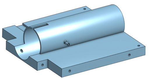
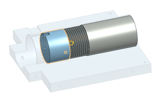
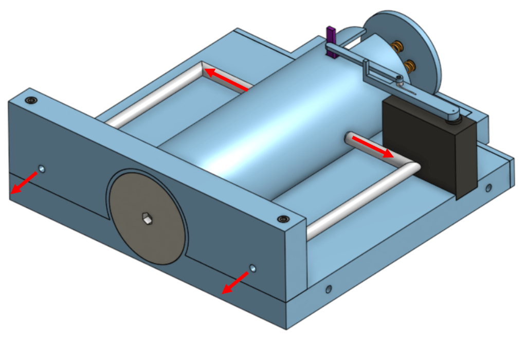
The base component of the dispersal device is where the various subassemblies and parts attach. Therefore, the design of the base is more complex than the other units involved. Images of the base can be seen in Figures 6 and 7 at different perspectives. The base’s middle is a cylinder to house the cartridge holder assembly and the puncture component. The puncture component is affixed in the cylinder and the holder assembly screws into the other side. Nozzles for gas distribution from the cartridge and puncture component are located on either side of the base cylinder. A representation of how the base, puncture component, and cartridge holder assembly interact can be seen in Figure 7 with the puncture component highlighted and the base made transparent for visibility.
Plunger & Spring Apparatus
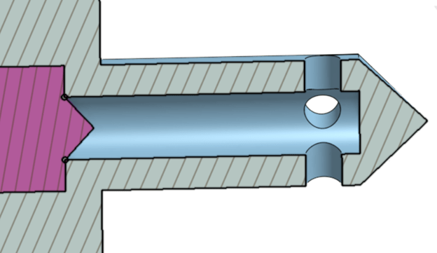
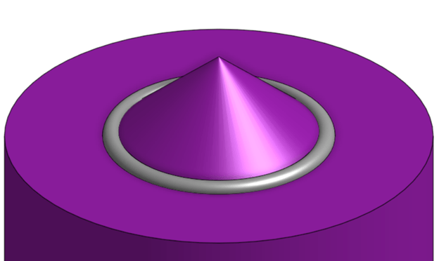
The challenge of controlled release of CO2 was solved via a plunger and spring apparatus. The plunger (Fig.8) rides within the base’s cylindrical portion and slides into the hollow center of the puncture component which seals the off the opening to the CO2 cartridge through the use of a rubber O-ring. The O-ring’s outer diameter is 0.1018 inches, which, when pressed into the 3/32 inch opening to the needle portion of the puncture component, creates a seal preventing CO2 from being released. This seal is depicted in a section view of the plunger/puncture component interface in Figure 9. A closeup on the O-ring and plunger is shown in Figure 10.

The release of gas is facilitated by the plunger being pulled back by a servo and then four springs snap the plunger back into the sealed position after the servo has succeeded in pulling back the plunger far enough for CO2 to have been released. Figure 11 depicts the assembly of the base (transparent), holder subassembly, puncture component, plunger, and spring mechanism. The spring mechanism consists of four springs and a side wall that is bolted into the base piece with two 3/8” long screws with #5-40 thread.
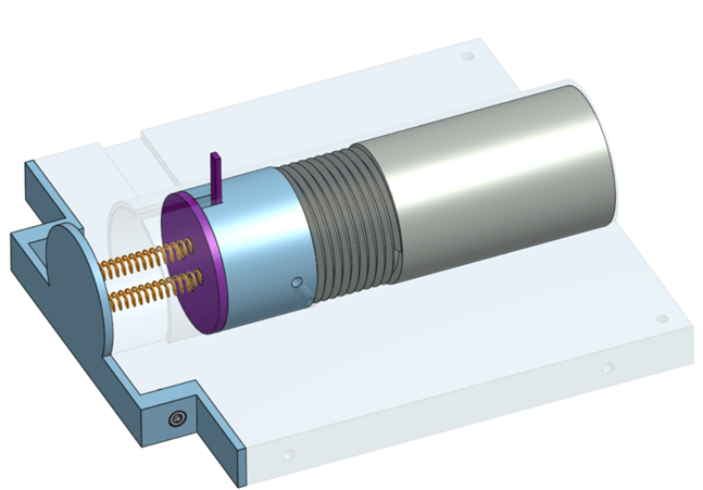
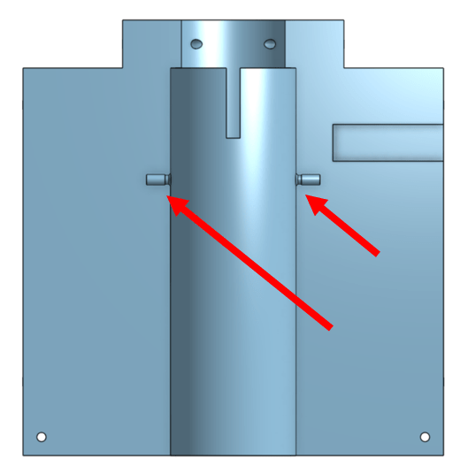
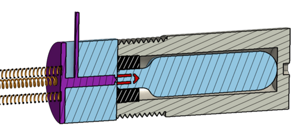
Figure 12 is a section view of the interaction of the plunger, puncture component, springs, and holder subassembly. It can be seen that the plunger seals off the flow of gas from the needle portion of the puncture component, pictured in red. In order for the air to be released, the plunger needs to be pulled back to allow for flow from the CO2 cartridge and out the nozzles on the base. A section view of the plunger being pulled back exposing the interior puncture component holes, which in turn line up to the nozzles on the base’s middle cylindrical portion. can be seen in Figure 13.

Servo Assembly
The goal of using springs with the plunger is to allow for quick cycling between the open and closed positions. This facilitates small bursts of CO2 and not one large expenditure of gas. The servo assembly, to operate the plunger, allows for the servo to perform the work of moving the plunger from the closed to the open position and for the springs to power plunger movement from the open to closed position. This process is depicted in Figure 14.

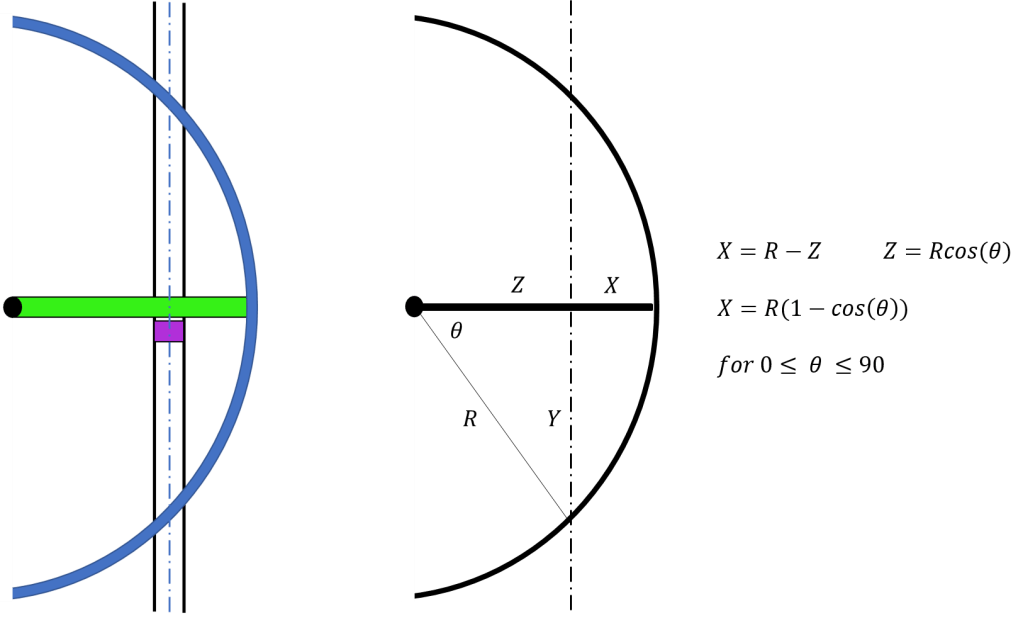
The switching of servo to spring power could have been accomplished by having the servo turn off after reaching the open position and allowing the springs to push the plunger back into the closed position. However, if this was done, the unpowered movement of the servo arm done by the springs could, over time, cause damage to the internal mechanisms of the servo. The solution for this was to use a servo arm of a specific length that, at a certain point of its rotation, swings off the plunger allowing the springs to push it back to the closed position. A simple diagram of this motion can be seen below in Figure 15. In order to determine the correct servo arm position, trigonometric equations (Fig. 15) were employed using the distance between the open and closed plunger locations. This distance was 0.25 inches. Using 0.25 for Y and a value of 2.60 inches for Z, which placed the pivot point of the arm 0,25 inches from the base edge, R and X were solved to equal 2.612 and 0.012 inches respectively. The X value corresponds to the amount the servo arm extends beyond the middle of the plunger. The middle of the plunger was used for the calculations as it was thought that after the arm passes the springs could overpower the servo and move the plunger back into the closed position. Therefore, if the edge of the plunger tab was used as the end point of Z, the servo arm may not complete its arc of motion before the springs pushed the plunger back. This would result in a servo that cycled the plunger without it ever reaching the open position. However, since the middle of the plunger was used as the end point of Z, the servo arm will most likely have to rotate to an angle slightly greater than the 5.5 degrees θ equals. This will have to be fine tuned with a working prototype.

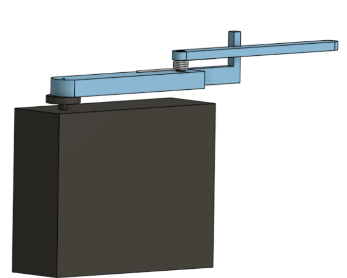
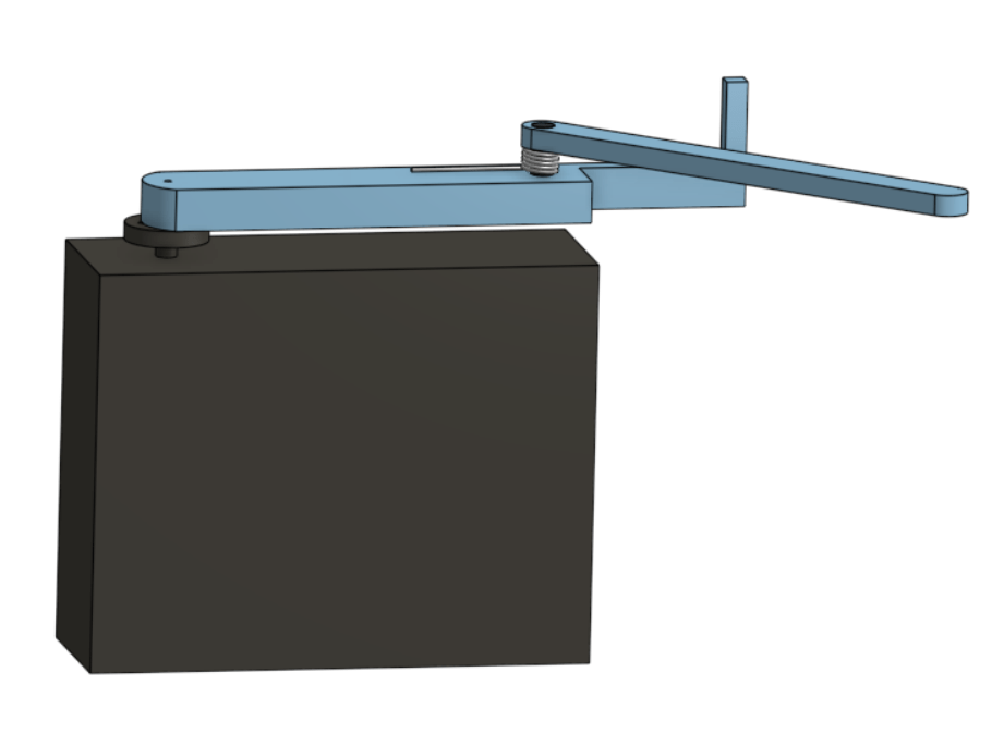
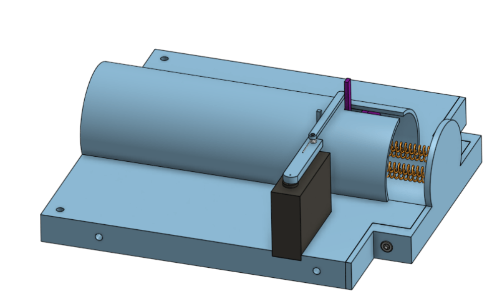
The servo arm is needed to be reset to its starting position when the plunger is closed as is illustrated by Figure 15. This could be done by having the servo arm rotate completely around; but this would increase the width of the device and be inelegant. A more sophisticated solution was to use a two-bar linkage system with a torsion spring for the servo arm that hinges in one direction, allowing for it to reverse its motion seen in Figure 15. This servo assembly is pictured in Figure 17. The servo arm two bar linkage is connected by a rivet which allows for rotation. The extending portion of the first bar prevents the second linkage bar from rotating counterclockwise while moving the plunger. The clockwise motion of the second bar allows for the servo arm to swing in reverse after moving the plunger (Fig. 18). Once the servo arm is past the plunger in its closed position the torsion spring realigns the second bar into position to move the plunger for another cycle. The servo assembly attached to the base assembly can be seen in Figure 19.
Dispersal of Gas
The directed dispersal of the CO2 gas flows out the base nozzles, through plastic tubing, into identical nozzles on an edge component, and out the opposite side. The plastic tubing and edge component are identified in Figure 20 and the air flow is shown in Figure 21. The edge component is attached to the base with two 1.5-inch-long screws with #4-40 thread.

The plastic tubing used is flexible with a 3mm inner diameter and 5mm outer diameter. The tubing stretches over the 3.5 diameter nozzle for a secure fit. At the distal end of the nozzle the diameter drops to 2.2mm. This should prevent the tubing from sliding off the nozzle as the end portion of the tubing would need to stretch back over the 3.5mm diameter portion. Figure 22 depicts the locations of the nozzles as well as a close-up image.

Cover
The final component for the CO2 dispersal device is the cover. The purpose of this piece is to protect the servo assembly and plastic tubing as well as neatly packaging the design so multiple dispersal devices can be used in unison while stacked. Below, in Figure 23, an isometric view of the cover attached to the dispersal device can be seen. The cover is attached by four of the 3/8” long screws with #5-40 thread.
Electronic Housing
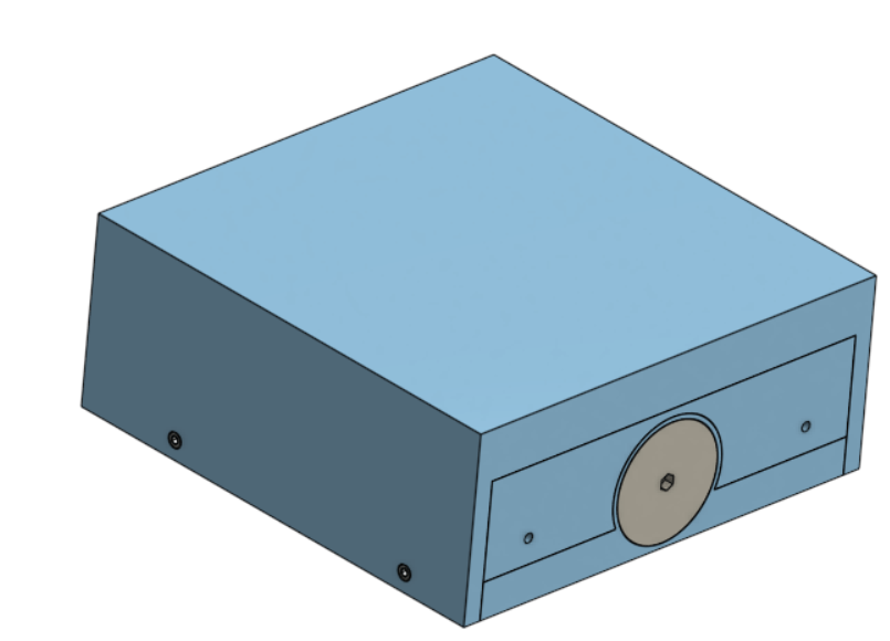
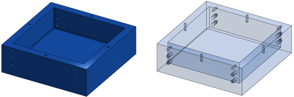
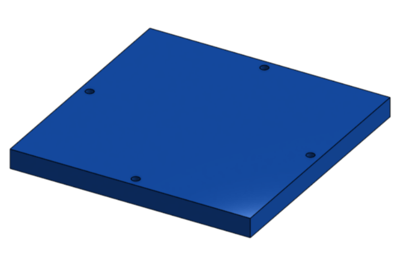
The housing for the electronic components, such as a power source and microcontrollers, of the new bug zapping design is pictured in Figure 24. The housing has a set of three holes near each corner (Fig. 25) for wire management and the attachment of supports. Four screw holes are located on the top plane of the housing for the housing cover (Fig. 26). The screws used to attach the supports and the cover are the same screw used in the CO2 dispersal subassembly, 3/8” long screws with #5-40 thread.

Supports
Supports were used to assembly the electronic housing, dispersal devices, and the zapping element of the bug zapper. Two different supports were used due to the separate facing directions of the two dispersal assemblies (Fig. 27) used in the bug zapper design. The goal of having the CO2 released in two directions was to increase the spread of CO2 to the surrounding area and thus attract more mosquitoes. The supports attach to the dispersal device cover at the opposite side from where the gas is released.
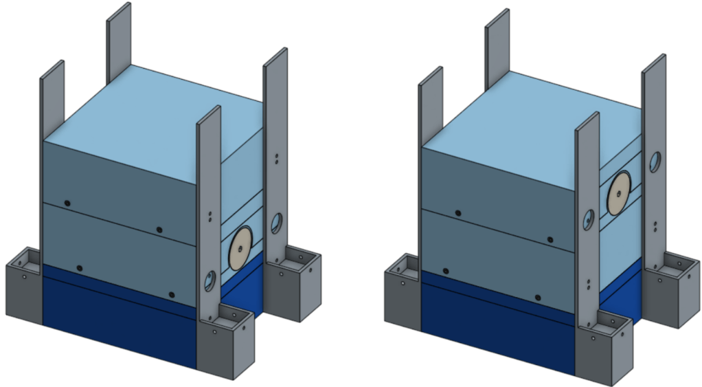
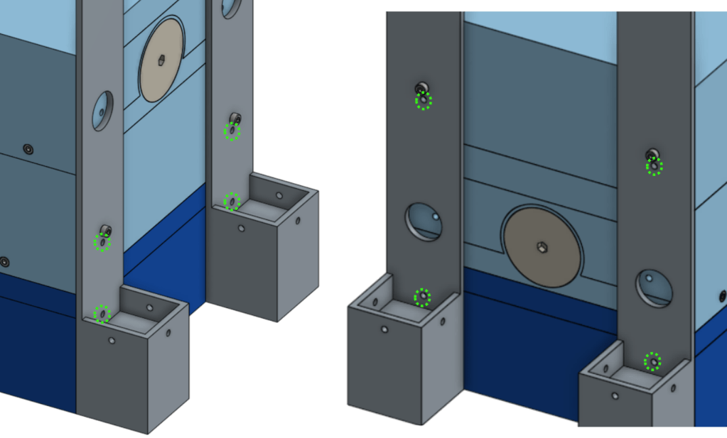
Figure 28 illustrates the interface between the dispersal device cover and the support. The screws, 3/8” long screws with #5-40 thread, used for attaching and the holes used for wire management are pictured.
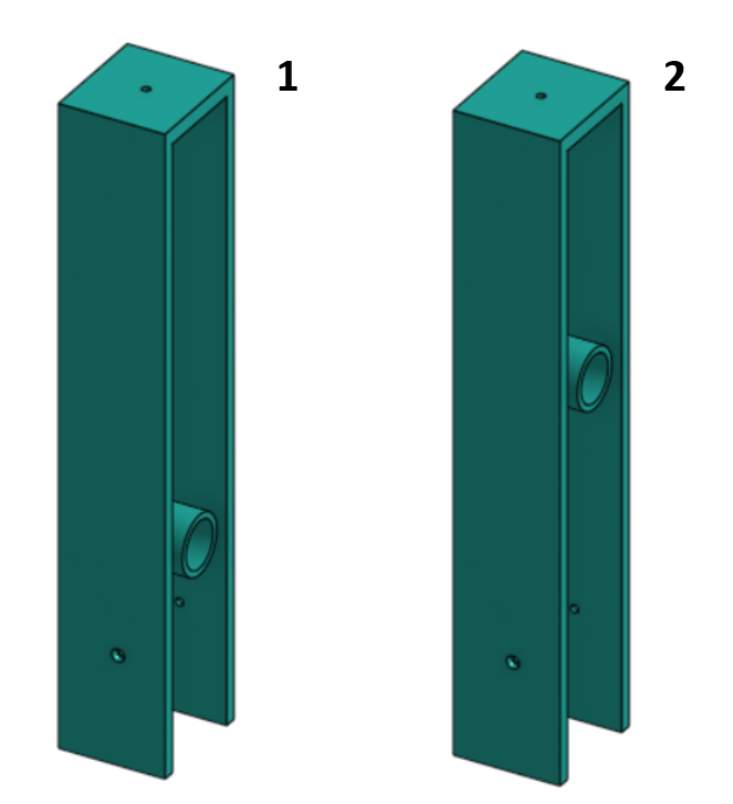
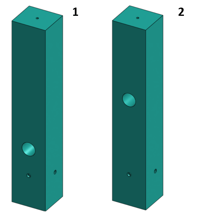
Covers were attached to the supports to enclose the wires leading from the dispersal assemblies to the electronic housing component. The covers attached to the foot of the supports with three screws, 3/8” long with #5-40 thread. Two separate cover designs were required to correspond to the varying height of the CO2 exit locations. The large holes found in the support designs to prevent blocking the release of CO2 were matched to hollow protruding cylinders in the support covers which allowed for the gas to flow through the hollow support assemblies. The two different cover designs are pictured below in Figure 29 and Figure 30.
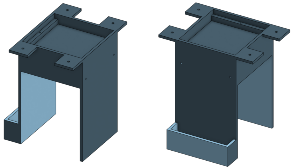
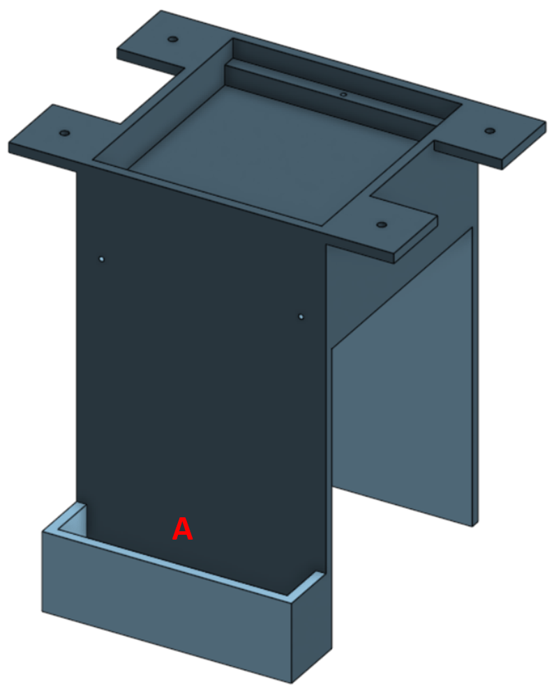
Shell
The shell part (Fig. 30) of the bug zapper design sits on the top CO2 dispersal device and attaches to the support covers. The shell component houses the wire mesh zapper, a tray for the lactic acid/human sweat analog, a syringe holder, and locations for handles to be attached to the device (Figs. 31 and 32). The syringe holder is to house the syringe to refill the human sweat analog tray through the wire mesh. Locations for wires to be fed into the hollow supports exist in the support components that attach to the top CO2 dispersal assembly (Fig. 33). The wires powering the wire mesh zapper will travel from the electronic housing, in the support column, and commencing its journey by entering the shell and connecting to the zapper.


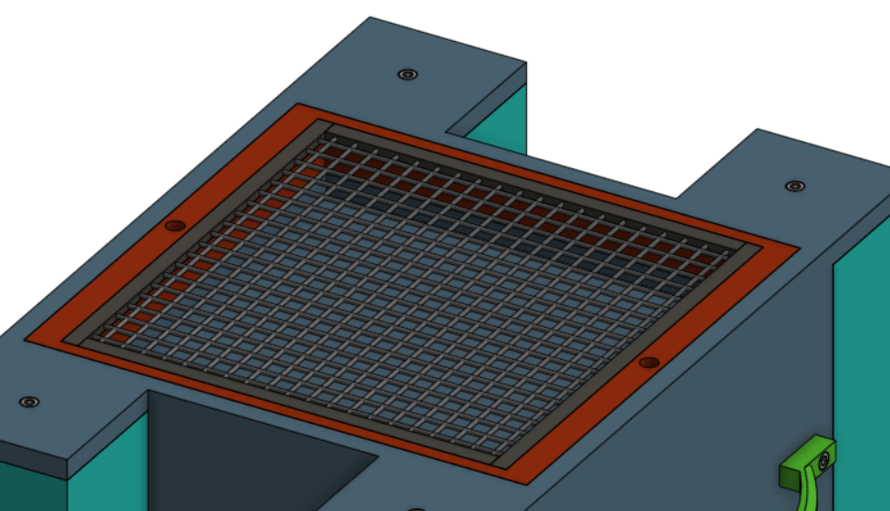
Wire Mesh Zapper
The wire mesh zapper attached to the shell component is pictured below (Fig. 34).
Handles
Two handles are attached to either side of the shell component to aid transport of the bug zapper assembly (Fig. 35). These handles are attached by two screws, 3/8” long screws with #5-40 thread.

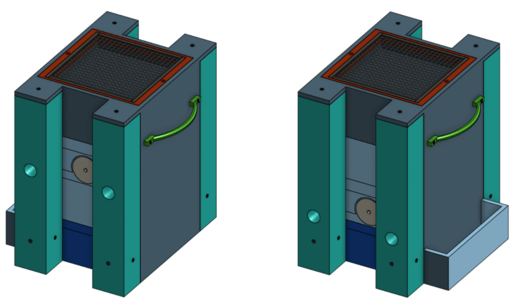
Final Assembly
The final assembly can bee seen in Figure 36. The design for a new way of eliminating mosquitoes incorporates CO2, heat from the electric mesh, and a lactic acid/human sweat analog as means of attraction. The efficacy of using these attractants in conjunction with a wire mesh zapper as a method of killing mosquitoes is unknown. However, despite the efficacy being unknown, the research suggests it has promise and could potentially reduce the death toll of non-biting insects.
The solution of the human sweat analog would need to contain lactic acid [4]; however, the concentration would need to be determined. The addition of electrolytes and other components of human sweat also requires study in order to create a successful human sweat analog.
I believe the prototype for a new way of eliminating mosquitoes documented here shows promise. It should be noted though that this is a prototype and therefore would require additional work and redesign before it could be considered a finished product.
References
[1] Frick, T. B., and D. W. Tallamy. 1996. Density and diversity of nontarget insects killed by suburban electric insect traps. Entomological News 107:77–82.
[2] Do Bug Zappers Work? Yeah—About As Well As Any Other Indiscriminate Wildlife Slaughter. (2020). Retrieved 19 August 2020, from https://www.nytimes.com/wirecutter/blog/do-bug-zappers-work/
[3] Baik LS, Nave C, Au DD, et al. Circadian Regulation of Light-Evoked Attraction and Avoidance Behaviors in Daytime- versus Nighttime-Biting Mosquitoes [published online ahead of print, 2020 Jun 28]. Curr Biol. 2020;S0960-9822(20)30826-5. doi:10.1016/j.cub.2020.06.010
[4] Birgit M. Steib, Martin Geier, Jürgen Boeckh, The Effect of Lactic Acid on Odour-Related Host Preference of Yellow Fever Mosquitoes, Chemical Senses, Volume 26, Issue 5, June 2001, Pages 523–528, https://doi.org/10.1093/chemse/26.5.523
[5] Gillies, M. (1980). The role of carbon dioxide in host-finding by mosquitoes (Diptera: Culicidae): A review. Bulletin of Entomological Research, 70(4), 525-532. doi:10.1017/S0007485300007811
[6] Greenfieldboyce, N. (2019, March 28). How Mosquitoes Sniff Out Human Sweat To Find Us. Retrieved August 21, 2020, from https://www.npr.org/sections/health-shots/2019/03/28/706838786/how-mosquitoes-sniff-out-human-sweat-to-find-us
[7] Crosman – CO2 Cylinder – 12g. (n.d.). Retrieved August 22, 2020, from https://www.animalgear.co.za/crosman-co2-cylinder-12g
2D Drawings
