BACKGROUND
Water damage doesn’t just occur while one is away from their place of residence and unable to take action to address the dilemma. Some instances of water damage can arise while one is home but otherwise occupied and not cognizant of the leakage until severe damage has transpired. Humanity has solved the parallel issue of fire damage with the installation of smoke alarms. Such alarms mitigate fire damage and loss of life as they allow for the fire to be halted before it becomes an inferno. Why is it then that alarms don’t exist for water damage? Granted, loss of life most likely isn’t a danger posed by water damage; however, loss of property, health, and savings are all real consequences. It’s estimated that the annual cost of water damage in the United States is thirteen billion dollars with approximately fourteen thousand Americans facing a water damage crisis every day [1]. These statistics show the issue prevalence and indicate the need for homeowners to possess prompt notification of an ongoing leak to mitigate the resulting harm.
PROBLEM DESCRIPTION
There exists a need for individuals to be notified about the presence of any ongoing leaks or water related issues that could result in damage in order for mitigating responses to be taken. To solve such a problem, a set of user requirements was formulated and is detailed in the following table (Table 1).
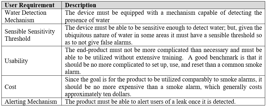
Water Detection Mechanism
The most essential requirement that must be fulfilled is that the device/solution be capable of detecting water where there shouldn’t be any. Without satisfying this goal, the device would be useless.
Sensitivity Threshold
The amount of water needed to trigger detection must be sensible as areas prone to water damage often have a harmless amount of water in the environment. This negligible amount of water must not be flagged by the device. Only excess amounts of water should trigger the alarm so as to not have an abundance of false positives.
Usability
Products targeted towards the public should always be designed with usability in mind. Complexity is rarely sought after for purchases. In addition, besides the marketability of the device, complex products are more likely to be unused and no one will be notified of ongoing water damage if the alarm was too convoluted to set up and use.
Cost
To match the widespread use of smoke alarms the solution must not be more expensive than an average smoke alarm which tend to go for ten dollars.
Alerting Mechanism
The product must be able to alert the user once water is detected. This could possibly be done by sound or lights.
BENCHMARKING
Several companies already sell alarms for leaks and excess water. A couple of these products are listed and detailed below. All the leak alarms use similar means of detecting water by using water as a means to complete a circuit.
Flood Buzz Water Leak Alarms
Flood Buzz [2] produces several water leak alarms, detailed in Figure 1 that are comparable in price to a smoke alarm. Their design appears to use water as the method to join two leads, or prongs, that are wired to an alarm. When the water branches the two leads the circuit is complete sounding the alarm. The models are powered by internal batteries.
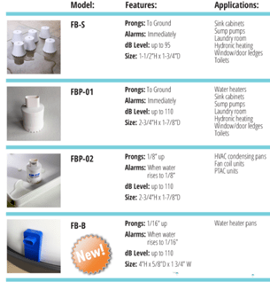
The difference in Flood Buzz’s models stems primarily around the height of the prongs from the ground. The prongs can be directly at ground level, 1/16’ off the ground, or 1/8” off the ground. For the latter two prong heights, the water level around the sensor would need to be 1/16” or 1/8” respectively for the alarm to sound.
All of Flood Buzz’s models are sufficiently loud enough for an alarm as they have a range of 95 to 110 decibels (dB). To determine if this range is sufficient a logical comparison to make would be to the minimum sound level required for smoke alarms. The National Fire Protection Agency (NFPA) requires smoke alarms to have a sound level of at least 75 A-weighted decibels (dBA) [3]. A-weighted decibels weigh frequencies within the human hearing range higher than those outside it. As long as Flood Buzz’s alarms don’t favor frequencies outside the human hearing range, which I am sure they don’t as that would be an odd choice for a product focused on alerting users, they should be meet the standard required of smoke alarms.
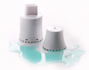
One issue I can envision with the Flood Buzz models is being unable to aesthetically integrate them into areas near bathtubs, showers, toilets, and sinks and therefore damaging their usability. Their raised platform draws attention that some customers would find objectionable. A secondary issue of false alarms could be an issue in those key areas mentioned previously. For example, if one was using the model where the leads go to the ground and they splash water on the floor while in the bathtub (Fig. 2), they could potentially set off the alarm. Using a model with higher leads likely solves the occurrence of false alarms; however, the water in that case would need to be at least 1/16” or 1/8” deep before the alarm were to go off. Depending on the location of the alarm, this could translate to massive flooding before water was detected.
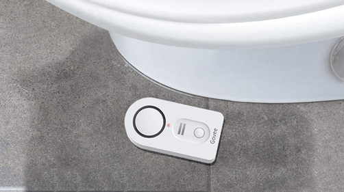
Govee Leak Sensor
Govee [4] also manufactures water sensor devices to catch leaks. Their product (Fig. 3) is incredibly similar to the models sold by Flood Buzz and appear to operate in the same fashion. When water is detected nearby users are alerted via an alarm with a maximum volume setting of 100 dB. The Govee sensors have the same drawbacks as the Flood Buzz sensors as they could be overly sensitive for some areas and bulky in appearance. The added feature present in the Govee model is that it is powered by batteries that can be replaced. The Govee model has a price that is similar to that of a fire alarm.
CONCEPT GENERATION
After a careful review of the problem description, user requirements, and benchmarking, concept generation was started. Rough ideas were generated initially with the mindset that the selected concept solution would then be polished.
Concept #1
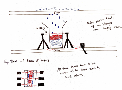
The first concept revolved around the utilization of technology used in garage door sensors. Garage door sensors work with a beam of infrared light being shot at a sensor. As long as the sensor detects beam the operation of closing the garage door is not interrupted. It isn’t until the sensor no longer detects the beam does the garage door cease to close and begin to open instead.
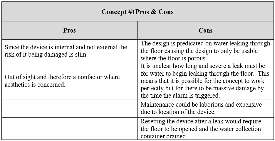
The proposed design, pictured in Figure 4, uses the interrupted infrared beam system to trigger an alarm. Water seeps through the floor and into a container underneath, gradually filling it. As the container fills, a buoyant plastic puck rises until it breaks the infrared light’s path which results in the alarm sounding. The switch to silence the alarm can either be on the ceiling of the floor below or in the room where leaks are being monitored. The pros and cons for this design are listed in Table 2.
Concept #2
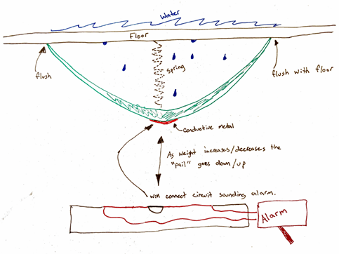
Concept #2 (Fig. 5) is quite similar to concept #1 as it too has a water collection container located underneath the floor and is dependent on water seeping through the floor to trigger the alarm. Water collects in the container which lowers via a spring as the weight of the water increases. Located on the bottom side of the container is a section of conductive metal. Once the metal reaches the circuit leads within the wall, an alarm is triggered by the completion of the circuit. The switch to shut off the alarm for this concept can be situated wherever, whether that be in the room monitored for leaks or in an adjacent location.
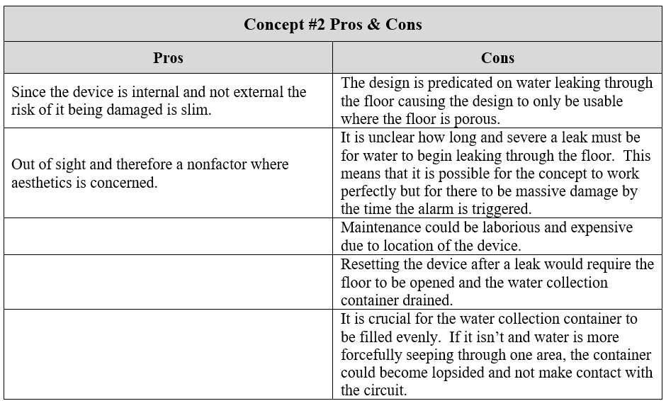
The pros and cons list for this concept is represented in Table 3. Given the similarity between concept 1 and 2, it is no surprise to find that there is large overlap between their respective pros and cons lists.
Concept #3
The idea behind this concept was to create an alarm system that mimicked a drain in appearance and accessibility. The device is comprised of two internal chambers where water must reach a certain level in the first chamber before it can begin to fill the second chamber. Once the water reaches the second chamber it would connect two circuit leads sounding the alarm. This two-chamber feature would help prevent false alarms in areas where the floor sometimes becomes slightly wet such as bathrooms as the water wouldn’t make it to the second chamber unless the amount was indicative of a leak.
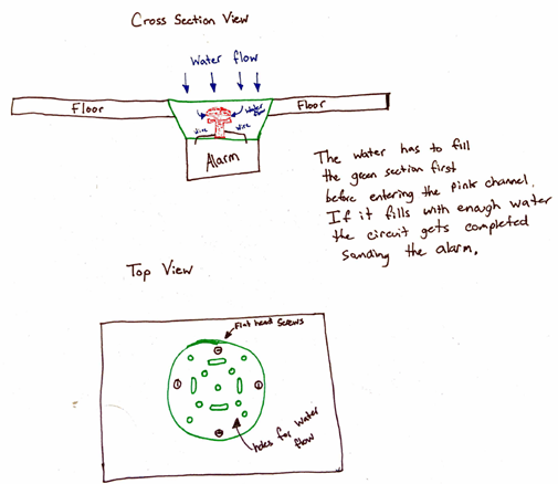
The pros and cons with this concept are listed in Table 4. The severity of the design’s drawbacks appears less than that of concepts one and two.

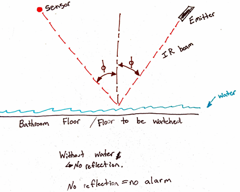
Concept #4
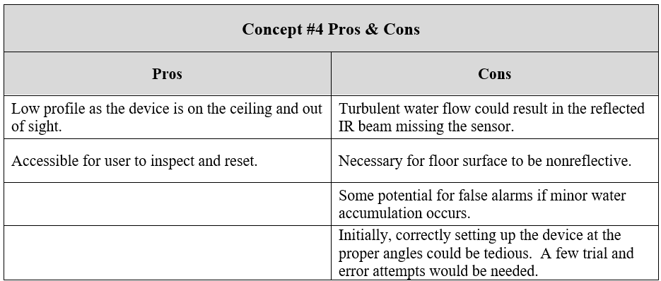
The final concept (Fig. 7) that was generated was inspired by the garage door technology mentioned for the first concept with a twist. Instead of the alarm being induced by a break in the IR beam it would be caused by the sensor detecting the beam. During a leak the water covering the floor would reflect the IR beam to the sensor causing the alarm to go off. The pros and cons of this design are listed in Table 5.
CONCEPT SELECTION
Concept selection was performed by using a Pugh chart (Table 6) to compare each concept to the user requirements. The user requirements were weighted out of ten in terms of their importance. The ability to accurately detect the presence of water was weighted a ten signifying it as the most important aspect. Cost was the weighted as the least important design aspect. The total point value for each concept was calculated by multiplying the concept’s user requirement scores with the corresponding weights and adding the products. Dividing by the maximum possible total, three hundred and ninety, resulted in the normalized score.
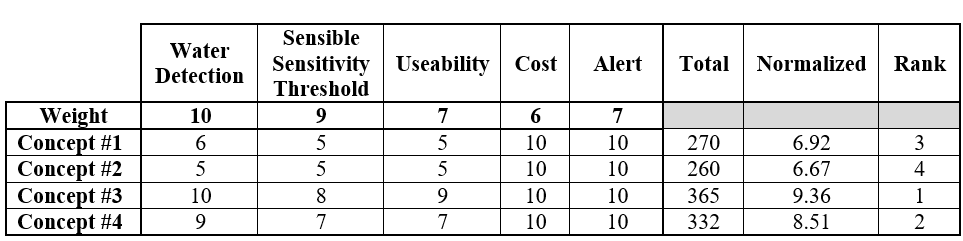
The cost and alert user requirements were nonfactors as the designs were comparable in those aspects with the costs ostensibly being similar and the alert mechanism for each design utilizing an audible alarm. Concept #3 received the highest point total and thus will be the selected design for the water alarm solution.
WATER ALARM DESIGN
The product can be broken up into three separate sections for closer examination. These sections are the main body, battery assembly, and floor interface.
Main Body
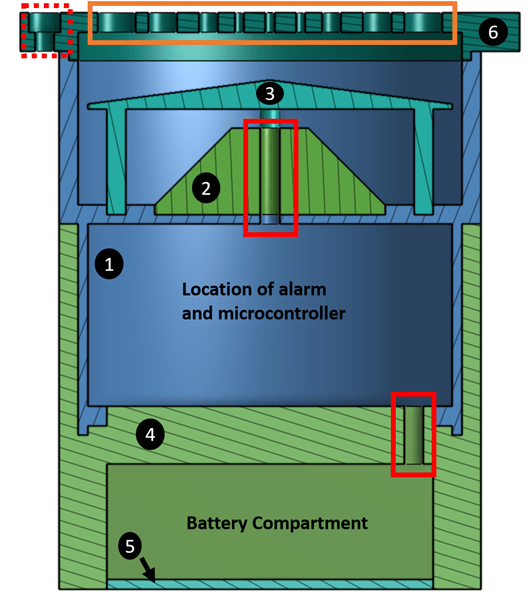
The main body of the device consists of three components: the main housing, water sensor platform, and water sensor shield. The main housing (Fig. 8 & 9) is an open-faced cylindrical component. The bottom half stores the microcontroller as well as the alarm and features edges on which the battery assembly attaches. The top half has a set of four cylindrical indents where the water sensor shield sits. The water sensor platform sits in the large central indent. The water sensor, consisting of unconnected leads that will be bridged by water, sits on this platform. Wires connecting the sensor to the microcontroller and alarm are threaded through the hole in the center of the main housing component. The top half also contains an edge on which the floor interface section rests and adheres to with glue.
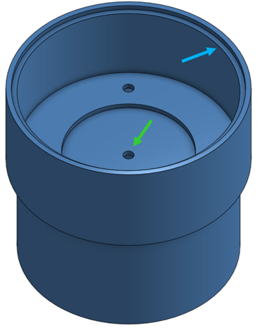
The water sensor platform and shield are pictured in Figure 10. The purpose of the water sensor platform is to raise the sensor so that water must fill the main housing to a certain level before reaching the sensor. This is to prevent the device’s alarm from sounding at any tiny amount of water that makes its way into it. The sensor shield’s job is to prevent the platform’s purpose from being undermined by a direct drip onto the sensor thus ensuring that the water level reach a certain height before the alarm is triggered.

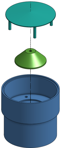
For further illustration of how the three components of the main body interact, an exploded view is pictured below in Figure 11. Both the sensor platform and sensor shield connect to the main housing component with the use of glue.
Battery Assembly
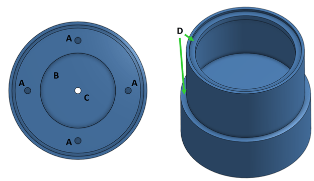
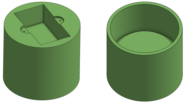
The battery assembly section houses the 9-volt battery used to power the device and consists of two parts, the battery housing and battery cover. The battery cover attaches to the battery housing with two quarter inch screws and the assembly attaches to the main housing edges shown in Figure 9 using adhesives. The battery housing element of this section is pictured in Figure 12 with multiple views and the battery cover is shown in Figure 13.
The top features of the battery assembly fit into and over the main housing component. A section view of the battery assembly looking at its front side is shown in Figure 14. The features that match up with the main housing are shown as well as the 9-volt battery’s wire management hole which leads to the main housing.
Floor Interface
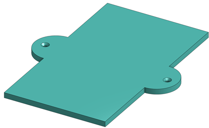
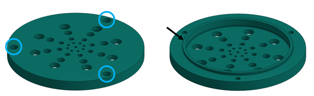
The protective lid is the only component that comprises the floor interface section of the device (Fig. 15). The purpose of this component is to provide a pathway for water to enter the device and to connect to the floor of the room being monitored. The component mimics a drain in appearance and function.

The protective lid has two types of holes on its face, drainage and screw holes (Fig. 16). The drainage holes are for water to flow through whereas the three counterbore screw holes affix the entire device to the floor. The other feature on the lid is found on its bottom side and is an edge that allows the lid to rest on the main housing component where it is attached with glue.
Final Assembly
An isometric view of the entire assembly can be seen in Figure 17.
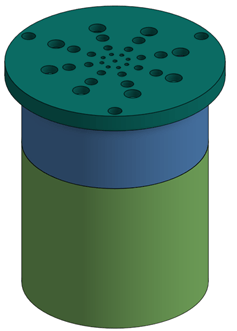
Figure 18 showcases a labeled section view of the full assembly. This view allows for a better understanding of how the individual components fit together.
The components of the water alarm are attached to each other through the use of adhesive glue. The only exception to this is the battery cover which attaches to the battery housing with two quarter inch countersunk screws. The areas where adhesive glue is applied are at the interfaces between the battery housing and the main housing, the main housing and the water sensor platform, the main housing and the water sensor shield, and the main housing and protective lid. These areas can be seen in Figure 19.

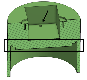
The amount of water needed to set off the alarm is easily calculated by finding the volume of the main housing sensor compartment at the height of the sensor and subtracting the volume of the sensor platform and sensor shield legs. The necessary dimensions to complete this calculation are depicted in Figure 20 along with a simplified diagram of the sensor stage. The equations (Eqn. 1-4) used to complete this calculation are depicted below.
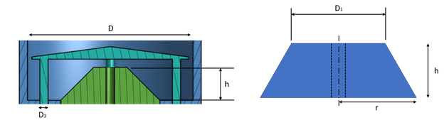
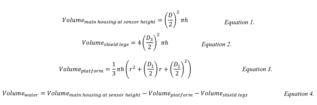
Using the dimensions of the main housing, sensor platform, and sensor shield depicted in Figure 20 and Equations 1 through 4, the volume of water was calculated to be 2.004 inches3. Without performing any validation testing this volume appears to be adequate for an alarm placed near the potential leak source. If the alarm is unable to be installed near the potential leak source, a modified design, where less water is required to trigger the alarm, would be needed.
CONCERNS/AREAS FOR POTENTIAL FUTURE REDESIGN
The device described above has three areas of concern that could warrant future redesign. The first area is the lack of an accessible on/off switch. As the devices currently stands the user would have to remove the alarm from the floor and disconnect the battery to silence an ongoing alarm. If one is focused on stopping a leak, the last thing they should need to do is look for a screwdriver to remove the alarm system in order to rid themselves of the noise. The redesign could consist of an on/off switch routed through the flooring to a convenient location or a wireless remote.
The second area of concern is the amount of water the device must take in before an alert is given to the user. Without physical testing it is unclear whether 2 cubic inches of water is too high of a threshold for catching leaks in time to prevent further damage. It’s possible this volume is adequate depending upon the position of the water alarm in relation to the source of the leak; however, further testing would be needed to be certain as a water alarm may need to be downsized to lower the amount of water needed.
The final concern area is the screw used in the CAD model [5]. The model screw is too expensive to be used in mass production and thus a different, although similar, screw would be required.
CONCLUSION
The final design detailed in the above section was designed around the user requirements listed in Table 1: water detection mechanism, sensible sensitivity threshold, usability, cost, and alerting mechanism. The design formulated is able to detect water via the water sensor that rests on the sensor platform. The elevated sensor platform and sensor shield combined create a sensitivity threshold that allows for some water to make its way into the alarm without triggering detection but not more than 2 cubic inches. The device does require some specialized skill with needing to be installed in the floor. However, this is no more complicated than some fire alarms which are directly wired to a home’s electricity. The water alarm’s cost will meet the user requirement as it necessitates no expensive materials and can be constructed out of plastic. Finally, a sound alerting mechanism will be more than adequate as this is the same technology utilized by fire alarms.
It is unclear how readily this product would be adopted by the public; but, the need to mitigate water damage exists and here lies a potential solution.
REFERENCES
[1] Water damage Statistics [2021]: Claim data & facts. (2020, April 15). Retrieved March 03, 2021, from https://ipropertymanagement.com/research/water-damage-statistics
[2] Flood Buzz Pro. (n.d.). Retrieved from http://floodbuzzpro.com/
[3] NFPA 72: National Fire Alarm and Signaling Code 2013 Edition. In NFPA National Fire Codes Online. Retrieved from http://codesonline.nfpa.org
[4] Making life smarter. (n.d.). Retrieved March 03, 2021, from https://www.govee.com/product/home-improvement/security
[5] 18-8 Stainless Steel Slotted Flat Head Screw. (n.d.). Retrieved March 04, 2021, from https://www.mcmaster.com/91781A430/
