Over the holidays my nebulizer I use to control my asthma decided to self destruct. As I was using it I noticed the air flow stopped despite the internal motor still running. I turned the machine off and also noticed that something was rattling around inside it. This was puzzling and frustrating; however, I soon started thinking that it would be interesting and educational to take the nebulizer apart, figure out its mechanism, and attempt to repair it.
Internal Mechanics
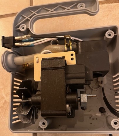
The view I was presented with when i opened the nebulizer was the following with a broken plastic piston (not pictured).
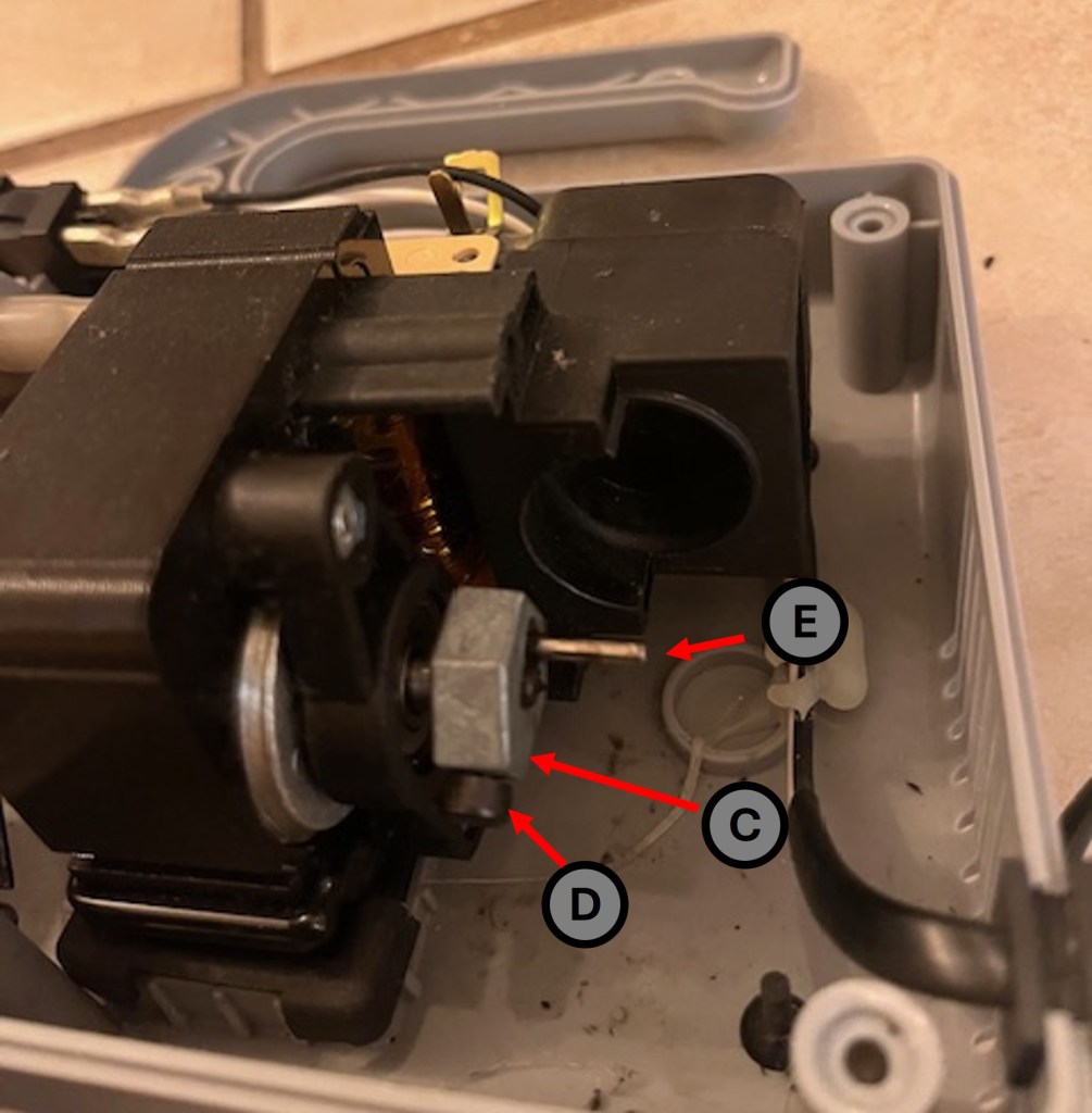
Now that the nebulizer had been cracked open the challenge became how does this thing work? I studied it for a few minutes and believe I was able to puzzle it out. The nebulizer has six main components: a motor, piston, piston chamber, air intake, air output, and cooling fan. The following image denotes the location of all these components with number labels and a bar placeholder for the piston that is not pictured.
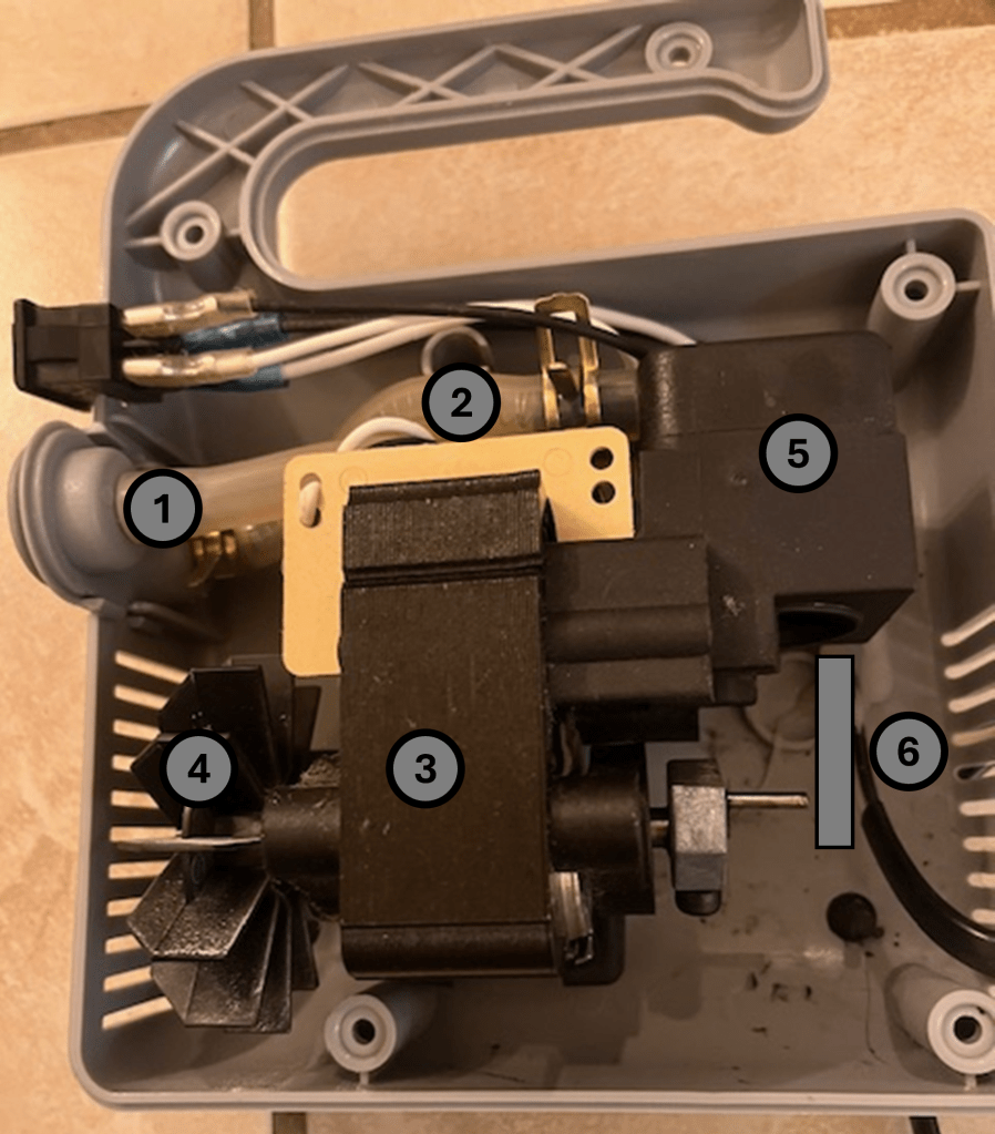
What I found incredibly smart and nifty was how the designer of the nebulizer used the motor axle to turn both the cooling fan and the piston. This allowed for less parts and a more compact and simple design.
The design works with the motor turning the axle connected to both the piston and cooling fan. The piston in collaboration with the piston chamber pulls air from the air intake hose and then when it is at a different point in its cycle pushes that air out the air output hose. That is essentially the entirety of the nebulizer mechanics. I did not disassemble the piston chamber as I still wanted to put this machine back together and use it and I was not confident I could dissemble the chamber without damaging anything. However, I do have a working theory as to how the chamber cycles air without sucking air from the output hose or pushing air out the input hose. The design would consist of two one way hinges with torsion springs attached to them so they want to stay closed at all times but can only open one way with force. I have diagramed this theorized design below in both its states; when pulling air in (Fig. 3) and when pushing air out (Fig. 4).
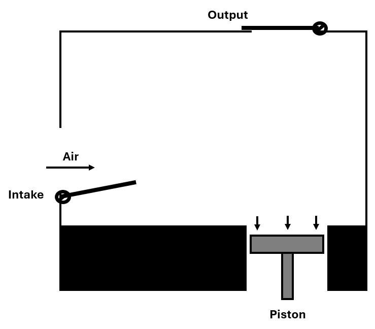
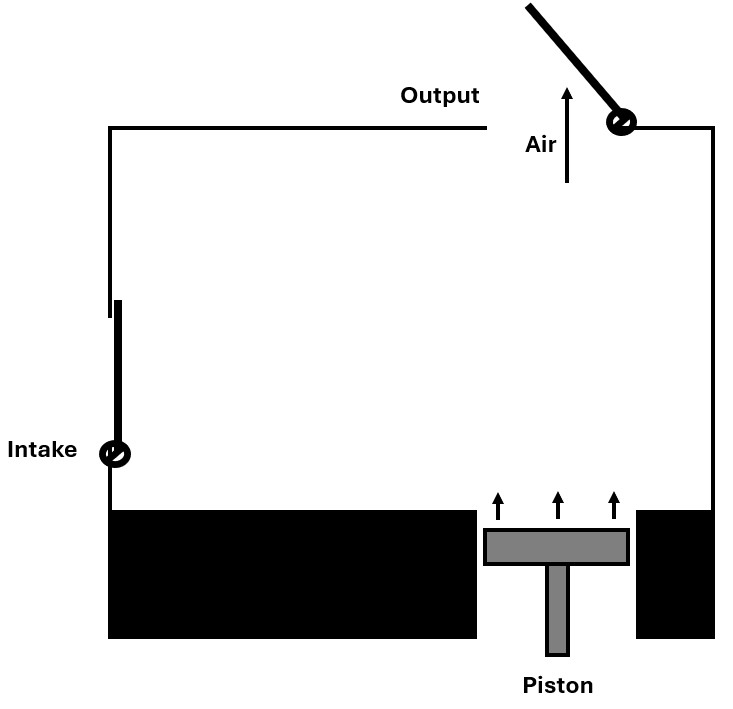
I can’t say for sure this is the design of the chamber the piston, intake hose, and output hose feed into but it must be similar if not this in order for the design to work.
Repair Work
Now that I had puzzled out the mechanics of the nebulizer I needed to go ahead and repair the plastic piston. I chose to repair the piston by simply gluing the two pieces back together with hot glue.
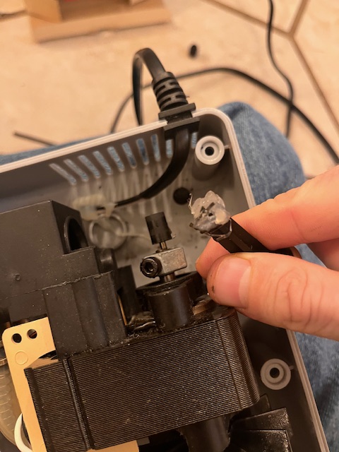
The piston rotates about a bar on the motor axle adapter (Fig. 6) which rotates about the motor axle.
In order to install the piston within the nebulizer the motor axle adapter had to be removed from the axle, the piston slid over the adapter bar, and the adapter reaffixed to the axle. Figure 7 depicts the adapter and piston assembly before being attached to the motor.

Results for Repair Attempt 1
Once the piston and adapter were reattached the only next move was to test my repair job by turning on the nebulizer. The piston held up for about two seconds before once again breaking into two pieces (Fig.8). Apparently hot glue alone did not provide enough structural integrity.
Continued Repair Work
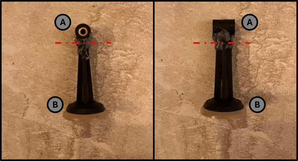
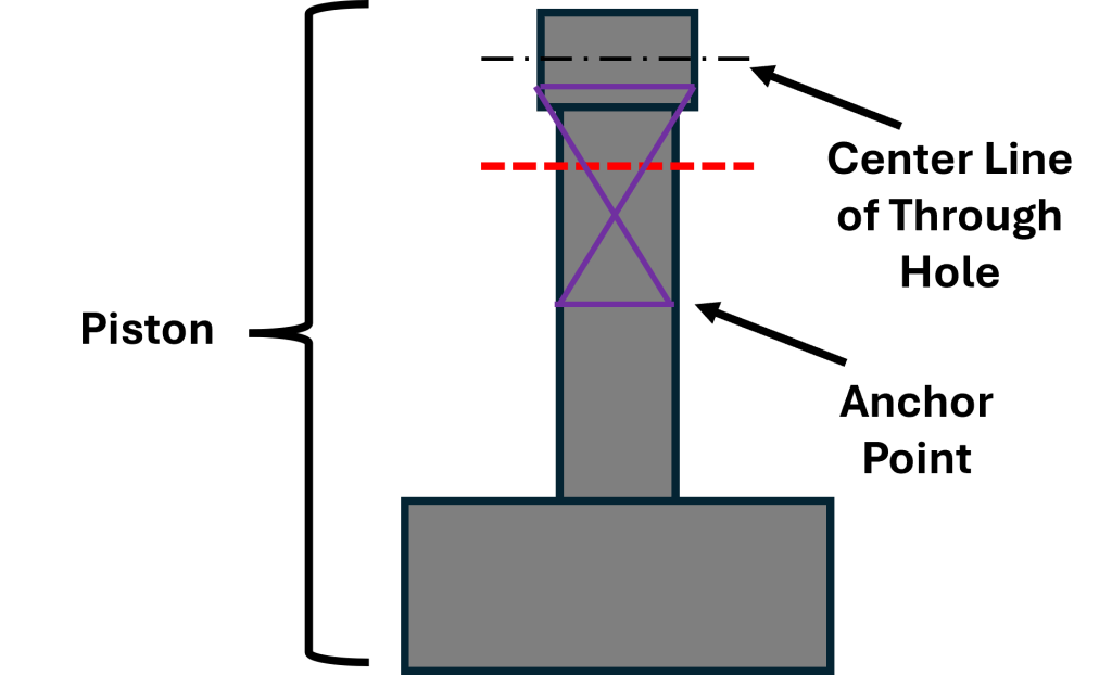
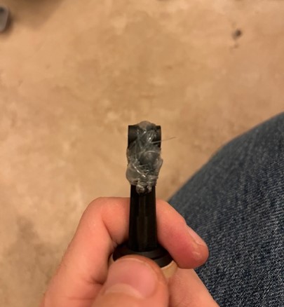
The problem as I saw it was that the surface area between the two broken pieces was not large enough for glue alone to solve and therefore I had to have a secondary element of structural integrity. After thinking for some time I decided to make use of the through hole that existed on the one end of the piston. I first used hot glue to once again reattach the two broken piston pieces. Then using fishing line I threaded it through the hole and kept making a figure-8 pattern pulling the two pieces together and anchoring each figure-8 pattern of fishing line with a dab of hot glue along the shaft of the piston after wrapping it around the circumference of the piston shaft. This can be seen below in Figure 9.
The actual end product using the combined efforts of hot glue and fishing line can be seen below in Figure 10.
Results for Repair Attempt 2
After the piston and adapter were reattached I turned on the machine to see if the piston would hold up. The second repair job held and continued to after several seconds of runtime.
Despite the piston holding up, I was unable to tell if the nebulizer was properly functioning without attaching a nebulizer kit to the output hose as it was possible the air pressure and velocity weren’t high enough to create the nebulizing effect. However, as you can see in Video 2, the nebulizer was properly functioning.
Conclusion
I surprised myself in being able to determine the inner mechanics of the nebulizer machine and repair it with the use of hot glue and something as niche as fishing line. I’ve always loved design challenges, or really any sort of engineering challenge, but didn’t expect to find one in a device I’ve been using for decades without a thought as to how it operated.
I did end up buying myself a new nebulizer machine as I didn’t want to learn about the upper limits of my repaired piston while in the middle of an asthma attack.
