Once again I found myself aimlessly browsing the homework portion of Reddit where users post homework problems and ask for help. I found one involving trusses similar to what I once would have found in my engineering statics homework questions. It’s been 10+ years since I solved a physics problem involving trusses; however, I was curious if I was still up to the task.
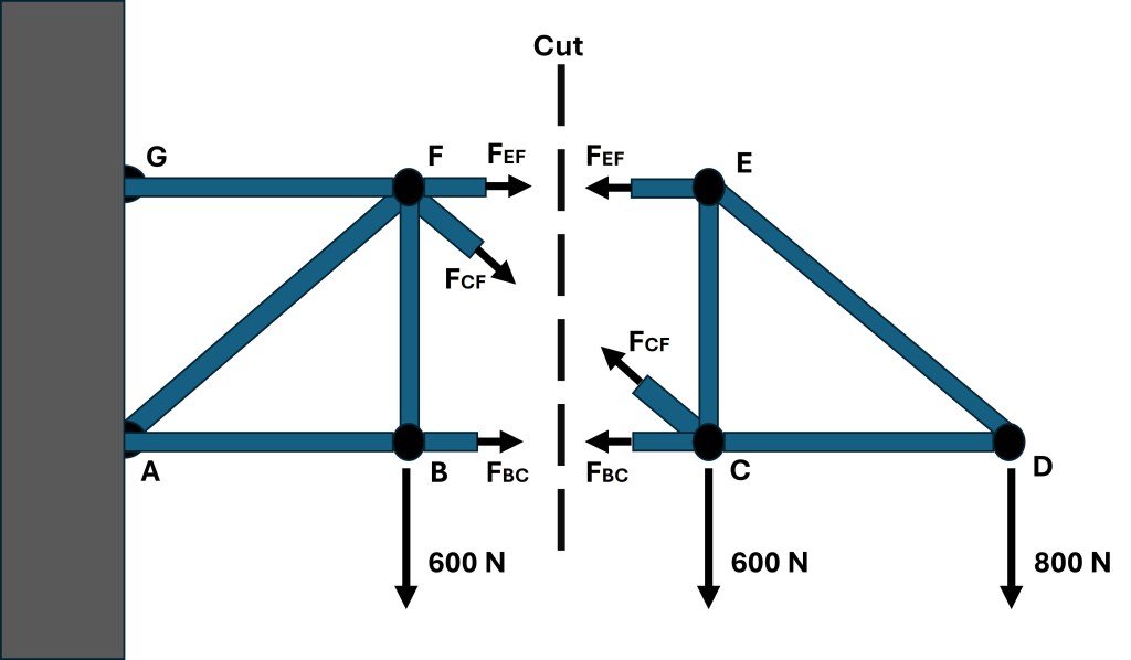
The problem is pictured below and asks for the force in trusses BC, CF, and FE to be found and for it to be noted whether the truss is in compression or tension.
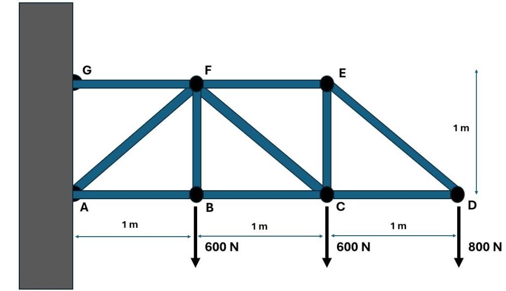
As I remember there are two ways to solve such a question: method of joints and method of sections. The method of joints operates by assuming if a system is in equilibrium so are the joints. Each joint can be sequestered from the system and subsequently analyzed using equilibrium equations. By using this method one would go from joint to joint until the unknown forces are found. The method of sections also involves using equilibrium equations but after sectioning the truss system.
Method of Joints
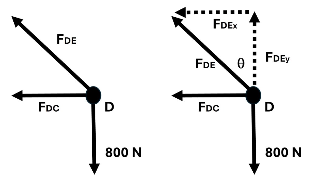
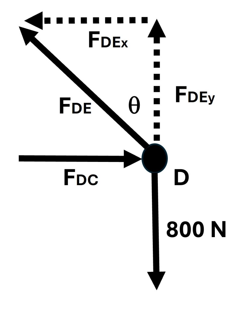
Joint D is where I started to solve this problem using the method of joints. Joint D was picked for its simplicity. The free body diagram of joint D is pictured below along with the x and y-force components of the force found in truss DE.
Step one in solving for the unknown forces at joint D is to use the equilibrium equation of setting all the y-direction forces equal to zero. This can be seen in the following series of equations along with the solution for the y-force component of the force found in truss DE.
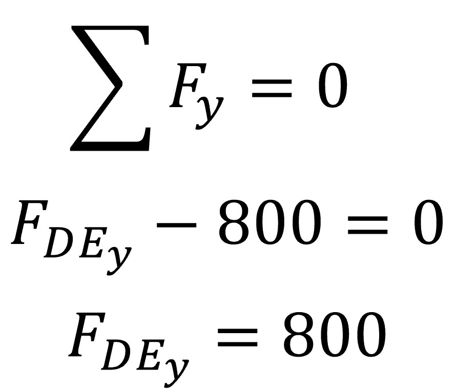
The force found in truss DE can now be solved for by using trigonometry.

Since the value for the force found in truss DE is positive we know the arrow in our free body diagram is correct. The arrow represents the force the truss DE is exerting on joint D and thus the force joint D exerts on truss DE will be in the opposite direction. Thus we know that truss DE is in tension.
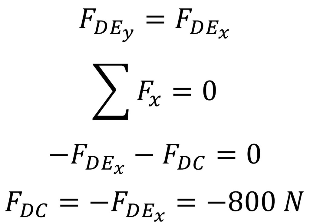
Knowing the trigonometric relation between the x and y-force components of the force found in truss DE and setting all the x-direction forces equal to zero, the force found in truss DC can be solved for by using the following.
The negative value for the force found in truss DC indicates that the direction of the arrow in joint D’s free body diagram is incorrect and must be reversed. The below image shows the correct arrow direction.
Based on the direction of the arrow for the force in DC, it can be said that truss DC is in compression.
The next joint to isolate and solve is joint E. The free body diagram of joint E is pictured in Figure 4. Based on the work done for joint D some of the forces found in joint E’s free body diagram are known.
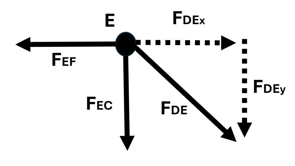
By starting with the y-direction forces we can determine the following.

Once again the negative value for the force found in truss EC indicates that the direction of the arrow in joint E’s free body diagram is incorrect and must be reversed. The below image shows the correct arrow direction.
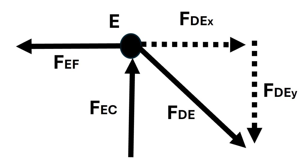
Due to the direction of the arrow for the force in EC, it can be said that truss EC is in compression.
The next step is to set all the x-direction forces equal to zero and solve for the force in truss EF. This is shown in the following set of equations.

Since the value for the force found in truss EF is positive, we know the direction of the force shown in Figure 5 is correct and thus truss EF is in tension.
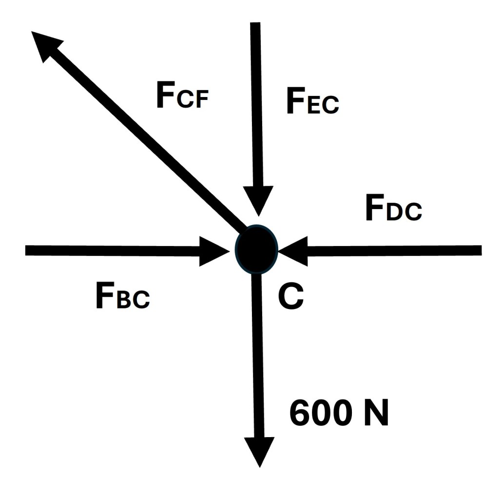
Joint C’s free body diagram is pictured below in Figure 6.
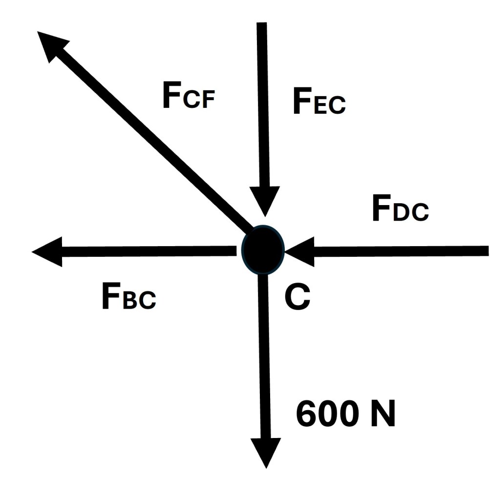
The forces in trusses DC and EC are known from the prior calculations. The first step with joint C is to set all the y-direction forces equal to zero and solve for the force in truss CF by first finding its y-component force. Once the y-component of the force in CF is known, trigonometry can be used to then find the force acting on the truss CF.
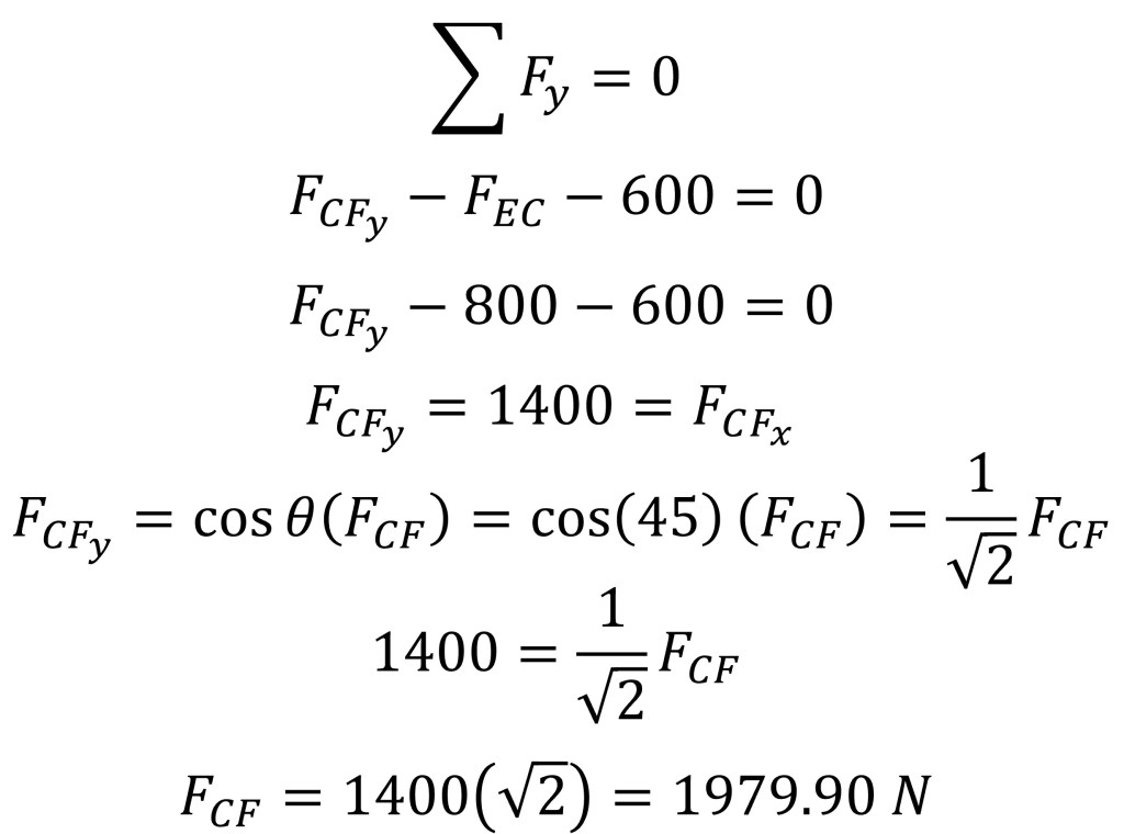
Since the value for the force found in truss CF is positive, we know the direction of the force shown in Figure 6 is correct and thus truss CF is in tension.
To solve for the force experienced in truss BC all the x-direction forces must be set to zero. This yields the following.
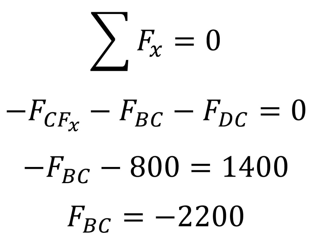
The negative value for the force found in truss BC indicates that the direction of the arrow in joint C’s free body diagram is incorrect and must be reversed. The below image shows the correct arrow direction.
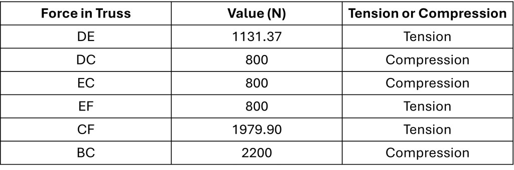
The direction of the arrow for the force in BC indicates that truss BC is in compression. The results of the method of joints calculations are summarized in the table below.
Method of Sections
To begin solving this problem using the method of sections I made a cut in the truss system along the trusses EF, CF, and BC. The result of this cut and the corresponding free body diagrams are shown below.
Setting all the y-direction forces found on the right side of the cut equal to zero results in the following.

Using trigonometry the force in CF can be solved for.
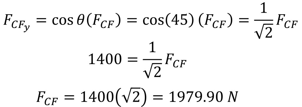
Since the value for the force found in truss CF is positive, the direction of the force shown in Figure 8 is correct and thus truss CF is in tension.
Taking the sum of moments around joint C and setting them equal to zero is a way to solve for the force in truss EF as the only two forces that apply a moment around joint C are the force in truss EF and the 800 N applied force to join D.
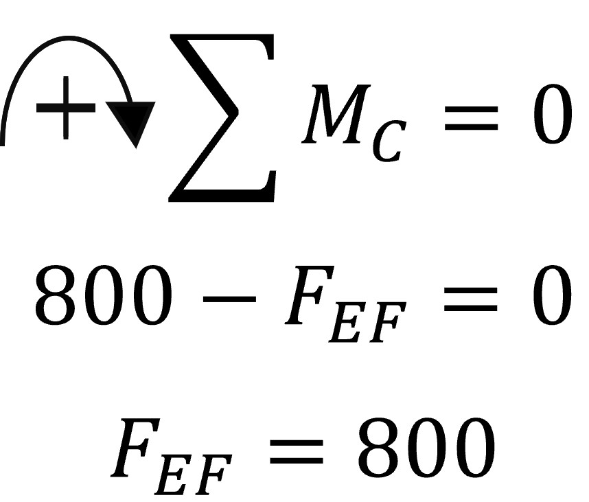
The sign of the force found in truss EF indicates that the truss is under tension. The last step is to solve for the force in truss BC and this can be done by setting all the x-direction forces found in the right section of Figure 8 equal to zero.

The negative value for the force found in truss BC indicates that the direction of the arrow in the section method free body diagram, found in Figure 8, is incorrect and must be reversed. The below image shows the correct arrow direction.

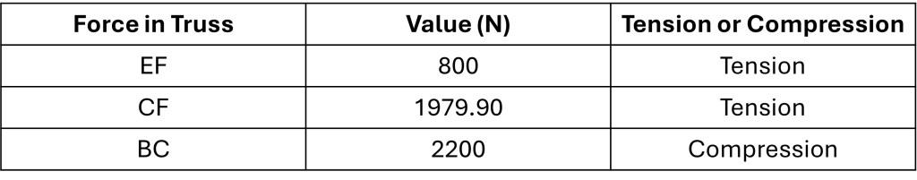
The direction of the arrow representing the force in truss BC shows that the truss is under compression. The below table summarizes the forces calculated by using the section method.
Summary
Both the method of joints and method of sections yielded the same results for the forces found in trusses EF, CF and BC. Based on the time spent with each method, the method of sections was the less time consuming way to go about tackling this problem.
Some may say this was a pointless exercise for me to go about performing since this problem was no different than the countless questions I completed for homework assignments at one point in my life. However, I enjoyed completing this task as it forced me to dig into my memory to remember how to solve such problems. In addition, I proved, at least to myself, that I haven’t forgotten everything I learned in engineering school.
